
Knuckle with thermal protector

Inactive Publication Date: 2007-05-17
ZF FRIEDRICHSHAFEN AG
View PDF20 Cites 2 Cited by
  • Summary
  • Abstract
  • Description
  • Claims
  • Application Information

AI Technical Summary

Benefits of technology

[0002] It is the object of the invention that the ball joint should incorporate an integrated thermal protector that will minimize the transmission of heat to the interior of the ball joint, in particular the heat generated by the brakes of the vehicle in order to prevent the rubber dust boot or cover from being damaged by the high temperatures generated in the surrounding area.

Problems solved by technology

Disc brakes, however, may easily reach 500° C. and the heat given off may therefore eventually break down the rubber or dust boot impairing its function, with the result that the cover is unprotected and the failure of the ball joint may take place in a short time.

Method used


Image

  • Knuckle with thermal protector
  • Knuckle with thermal protector
  • Knuckle with thermal protector

Examples


Embodiment Construction

[0012] The ball joint with integrated thermal protector proposes a clearly satisfactory solution in comparison with other solutions adopted previously in terms of functional efficacy, installation and reduction of costs.

[0013] The use of this ball joint with thermal protector reduces costs considerably in relation to the use of shields on the disc brakes, not only because it is the case of a protection element of smaller size and weight, but also due to the reduction in installation operations and in the number of components.

[0014] Furthermore, the thermal protector has an added feature in that it acts as a means of protection against the damage that the ball joint might suffer during handling, as it replaces the plastic cap normally used for this purpose.

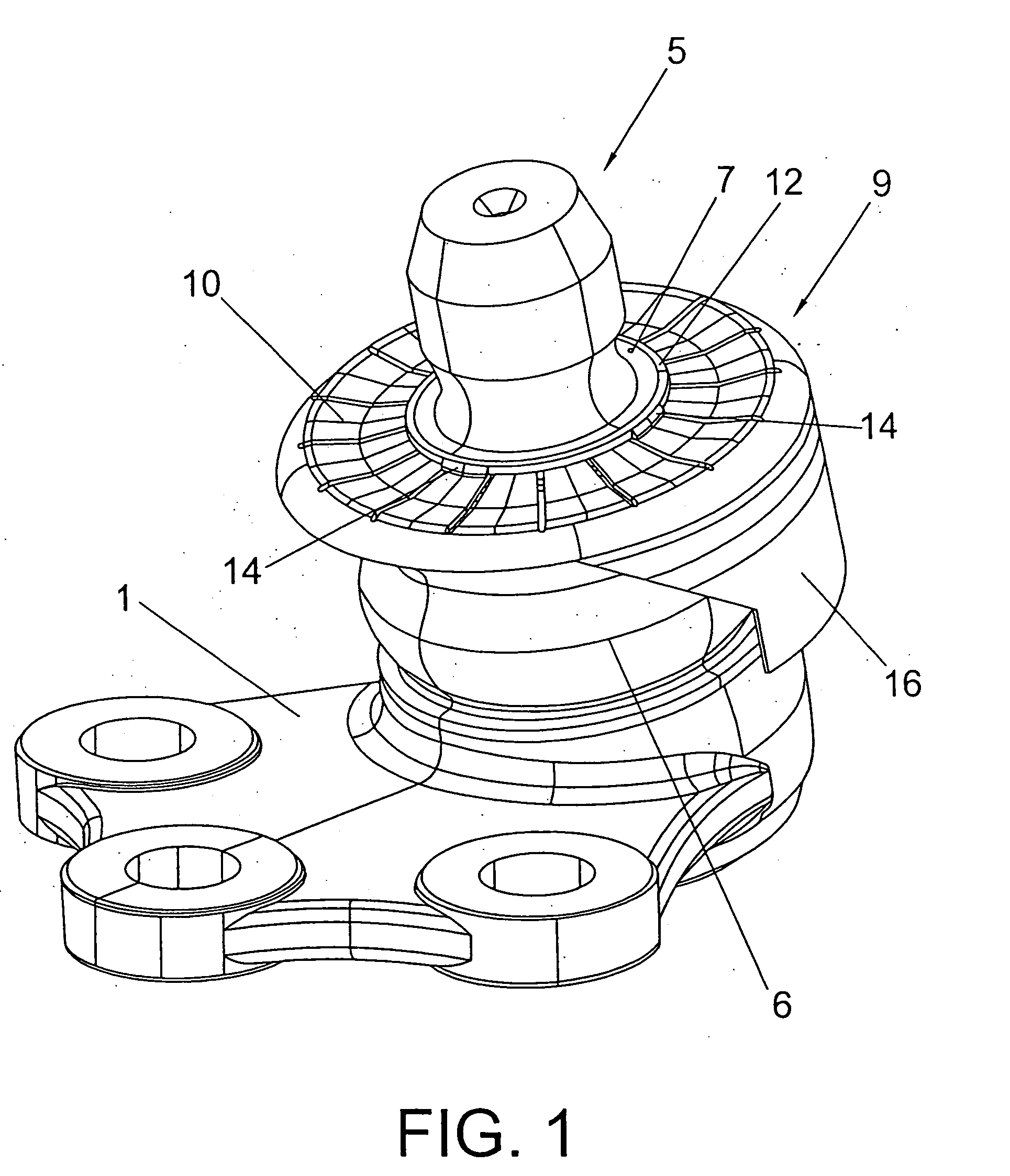
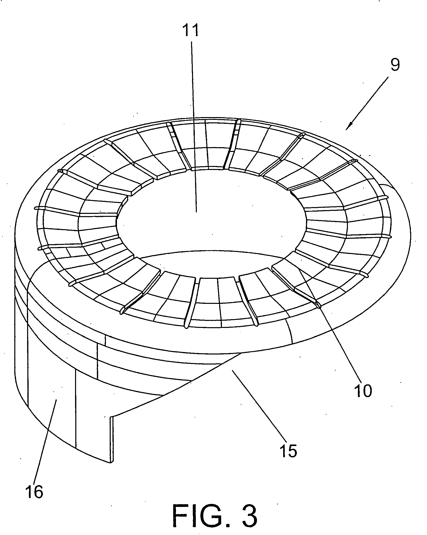
[0015] Integration of the thermal protector in the ball joint is therefore the basic object of this invention, since it is designed to cover the dust boot normally fitted to the ball joint, which is provided with a connecting ri...


PUM


Abstract

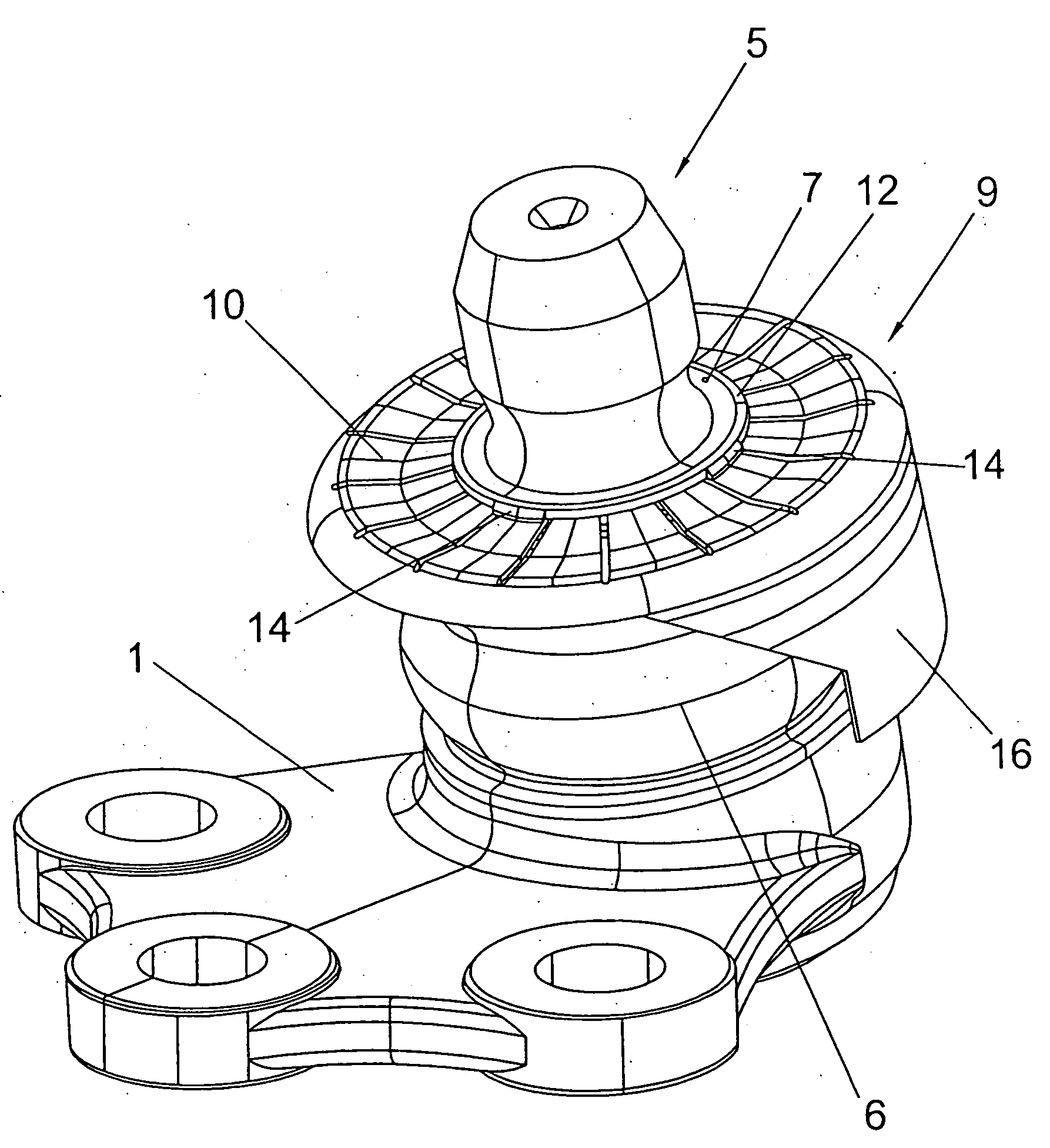
Of application for suspension and steering systems and / or stabilizer bars which are located in the vicinity of a source of excessive heat generation such as a brake, it basically incorporates a thermal protector (9) integrated in the ball joint which presents a series of flexible radial plates (10) on its upper face defining interiorly a circular opening (11) which is attached to a connecting ring (12) previously fixed to the neck (7) of the dust boot (6) by overinjection or pressure and / or gluing, so that the thermal protector (9) covers the dust boot (6) in order to protect it from the high temperatures generated in the surrounding area.

Description

OBJECT OF THE INVENTION [0001] The present invention refers to a ball joint of the type used in vehicle suspension and steering systems or stabilizers bars fitted with a dust boot to prevent the entry of dirt. [0002] It is the object of the invention that the ball joint should incorporate an integrated thermal protector that will minimize the transmission of heat to the interior of the ball joint, in particular the heat generated by the brakes of the vehicle in order to prevent the rubber dust boot or cover from being damaged by the high temperatures generated in the surrounding area. [0003] It is also an object of the invention that the thermal protector should be perfectly integrated in the ball joint-with the additional assistance of a connecting ring, affixed previously to the dust boot on which the protector is suitably attached. BACKGROUND OF THE INVENTION [0004] On vehicle suspension and steering systems it is common to make use of ball joints to interconnect components in su...

Claims


Application Information

Patent Timeline
IPC IPC(8): F16D1/12B60G7/00B62D7/16F16C11/06F16C17/24F16F9/38
CPCB60G7/005B60G2204/416B60G2204/4308B62D7/166F16C11/0619F16C11/0671F16C17/24F16F9/38F16C2202/24F16C17/243F16C2326/24F16C2326/05
Inventor IZQUIERDO NUNEZ, JOSE RAMONCANIBANO ALVAREZ, ESTEBANTEIJEIRO CASTRO, RAFAEL
Owner ZF FRIEDRICHSHAFEN AG
Learn More