
Noise reduction device and pneumatic tire provided with the same

a technology of noise reduction device and pneumatic tire, which is applied in the direction of inflatable tyres, vehicle components, tyres, etc., can solve the problems of cavernous resonance, tread portion vibration, and decrease the yield strength of the band member, so as to improve the high speed durability and minimize the temperature of the band member

Active Publication Date: 2020-10-13
YOKOHAMA RUBBER CO LTD
View PDF33 Cites 0 Cited by
  • Summary
  • Abstract
  • Description
  • Claims
  • Application Information

AI Technical Summary

Benefits of technology

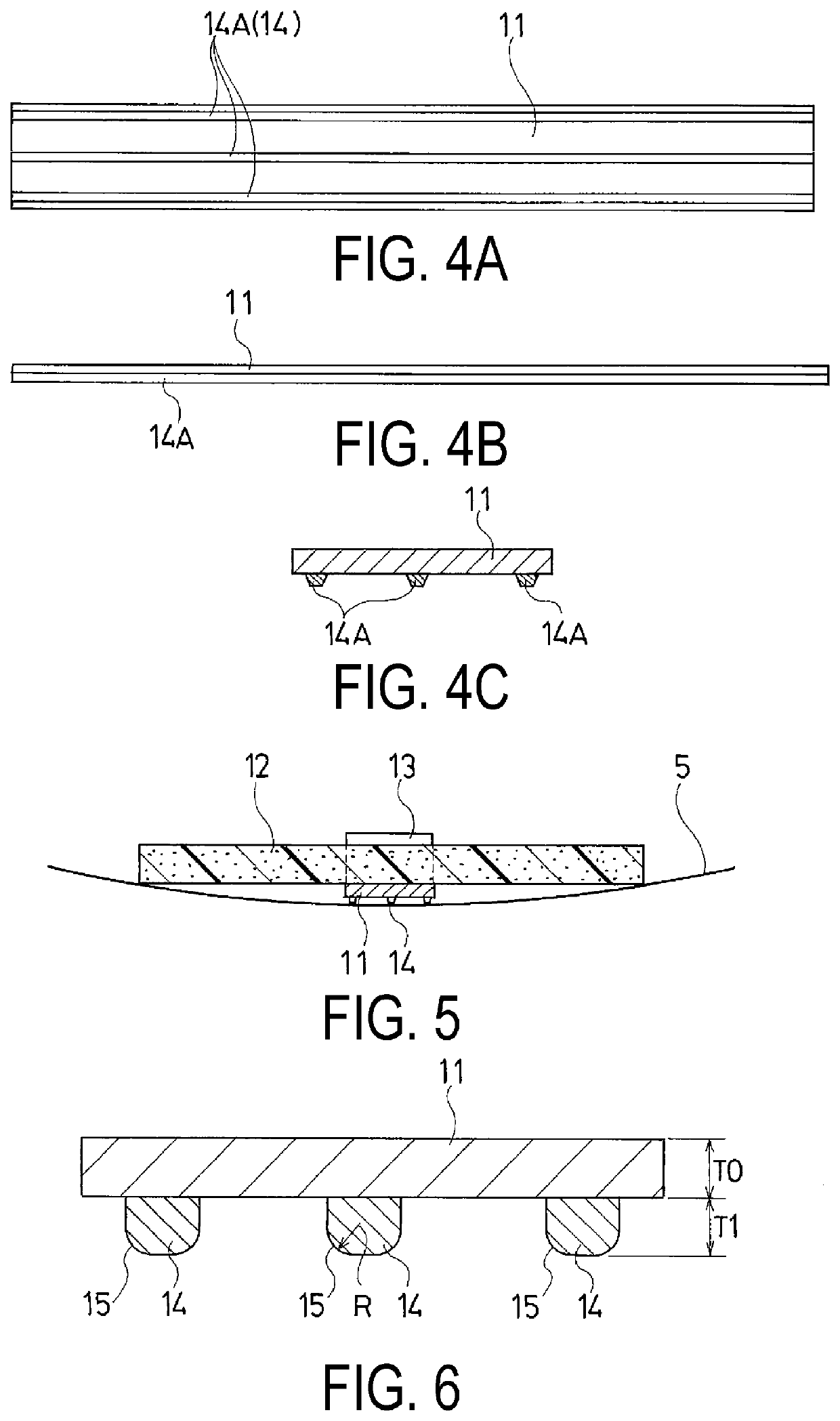
The present technology provides a noise reduction device for a pneumatic tire that minimizes heat build-up and improves high-speed durability. The device includes a band member with a raised portion that comes into contact with the tire inner surface and reduces heat transfer. The band member also has a chamfered portion at the edge of the raised portion to prevent damage to the tire inner surface. The raised portion can be continuous or intermittent and repetitive, and it can include a plurality of raised portions that come into contact with the tire inner surface. The raised portion is preferably from -50% to +100% of the band member's thickness. The noise reduction device also includes a sound absorbing member that is fixed to the band member through a locking member made of thermoplastic resin. Overall, this technology helps to reduce tire running noise and improve high-speed performance.

Problems solved by technology

One of the causes of the noises generated by a pneumatic tire is a cavernous resonance resulting from vibration of the air with which the tire is filled.
When a tire is rolled, uneven road surfaces cause a tread portion to vibrate.
Nevertheless, because the band member of the noise reduction device described above is made of a thermoplastic resin, heat generated in the pneumatic tire during travel is transmitted from the tire inner surface, decreasing a yield strength of the band member.
Then, when the increase in travel speed significantly increases a centrifugal force applied to the band member while the yield strength of the band member is in this decreased state, the band member deforms, possibly resulting in band member failure.

Method used


Image

  • Noise reduction device and pneumatic tire provided with the same
  • Noise reduction device and pneumatic tire provided with the same
  • Noise reduction device and pneumatic tire provided with the same

Examples


examples

[0043]Noise reduction devices of a Conventional Example, Comparative Examples 1 to 3, and Working Examples 1 to 6 were manufactured. Each of the noise reduction devices included a band member made of a thermoplastic resin formed into a ring shape along a tire inner surface, and a sound absorbing member made of a porous material bonded to the band member. Each of the sound absorbing members was arranged to be fitted onto the tire inner surface with the help of an elastic restoring force of the band member. Each of the band members was given a different configuration. These noise reduction devices are suitable for a pneumatic tire of a tire size of 245 / 50R18 100 W.

[0044]In the Conventional Example (standard), the thickness of the band member was 1.0 mm, and the outer circumferential surface of the band member was a flat surface without any raised portions. In the Comparative Examples 1 and 2 and the Working Examples 1 to 6, the thickness of the band member was 1.0 mm, at least one rai...


PUM


Abstract

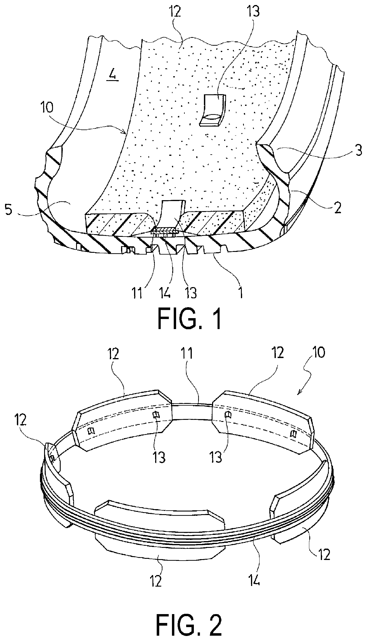
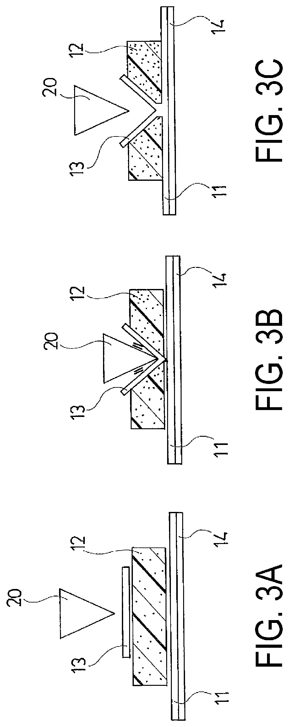
A noise reduction device (10) according to the present technology includes a band member (11) made of a thermoplastic resin formed into a ring shape along a tire inner surface, and a sound absorbing member (12) made of a porous material bonded to the band member (11). The sound absorbing member (12) is arranged to be fitted onto the tire inner surface with the help of an elastic restoring force of the band member (11), the band member (11) includes at least one raised portion (14) provided on an outer circumferential surface thereof, and the outer circumferential surface of the band member (11) has a contact area when in contact with a smooth surface in a range of from 10% to 80% of the projected area of the band member (11).

Description

TECHNICAL FIELD[0001]The present technology relates to a noise reduction device fitted onto a tire inner surface and a pneumatic tire provided with the same. More specifically, the present technology relates to a noise reduction device that minimizes an increase in the temperature of a band member during travel and enables an improvement in high speed durability, and a pneumatic tire provided with the same.BACKGROUND ART[0002]One of the causes of the noises generated by a pneumatic tire is a cavernous resonance resulting from vibration of the air with which the tire is filled. When a tire is rolled, uneven road surfaces cause a tread portion to vibrate. The vibrations of the tread portion cause the air inside the tire to vibrate, which produces this cavernous resonance.[0003]As a method for reducing noise caused by such cavernous resonance, providing a sound absorbing member within a cavity portion formed between the tire and the rim of the wheel has been proposed. More specifically...

Claims


Application Information

Patent Timeline
IPC IPC(8): B60C5/00B60C19/00B29D30/06
CPCB60C19/002B60C5/00B29D30/0681B60B2900/133
Inventor NARUSE, MASAHIRO
Owner YOKOHAMA RUBBER CO LTD
Learn More