Electrical rotating machine with improved heat sink cooling

a technology of electric rotating machines and heat sinks, which is applied in the direction of magnetic circuit rotating parts, magnetic circuit shapes/forms/construction, windings, etc., can solve the problems of short heat transmission path, insufficient output performance, and loss of heat sinks, so as to prevent the electrical potential of heat sinks, reduce heat transmission, and ensure the effect of heat transfer

Inactive Publication Date: 2014-10-07
MITSUBISHI ELECTRIC CORP
View PDF21 Cites 1 Cited by
  • Summary
  • Abstract
  • Description
  • Claims
  • Application Information

AI Technical Summary

Benefits of technology

[0009]The present invention has been made to solve the above-described problems, an object of the present invention is to provide a highly reliable compact electrical rotating machine by minimizing transmission of heat generated from a stator winding to an inverter circuit, and by preventing the heat sink from having an electrical potential.
[0011]The electrical rotating machine according to the present invention includes a rotor having a field winding, a stator having a stator winding, arranged so as to surround the rotor, a housing having a load side end fixed to the stator, and a heat sink assembly arranged inside the housing, having switching elements for controlling the field winding and the stator winding mounted on a heat sink. The heat sink assembly is fixed on an inner surface of an anti-load side end of the housing, having a supporting member interposed therebetween, the anti-load side end being axially opposite to the load side end with respect to the heat sink assembly. Therefore, it is possible to elongate a path of heat transmitted from the stator winding to the heat sink without increasing the overall length, in the rotation axis direction, of the electrical rotating machine, and accordingly, it is possible to reduce the effect of the heat on the switching elements.

Problems solved by technology

In addition, a loss is caused by the length of a harness connecting the electrical rotating machine and the inverter.
The electrical rotating machine thus attempts to meet the specification temperature, resulting in insufficient output performance.
Further, since a power circuit unit and a brush holder are arranged outside the rear bracket, a length of the rear bracket in an axial direction is short, and consequently a heat transmission path becomes short.
The insulating material tends to deteriorate over time, which leads to deterioration in fastening power, and leads to component damage which is accelerated by vibration of a vehicle body.
Further, when the heat sink has an electrical potential, in order to secure safety against collision, a sufficient spatial distance needs to be arranged between a material having no electrical potential such as the housing, and the heat sink, which leads to a problem of upsizing of the entire machine.
However, the insulating coating is expensive, and, in addition, will be deteriorated by salt water.
That is, the insulating coating is insufficient from a viewpoint of reliability.

Method used


Image

  • Electrical rotating machine with improved heat sink cooling
  • Electrical rotating machine with improved heat sink cooling
  • Electrical rotating machine with improved heat sink cooling

Examples


first embodiment

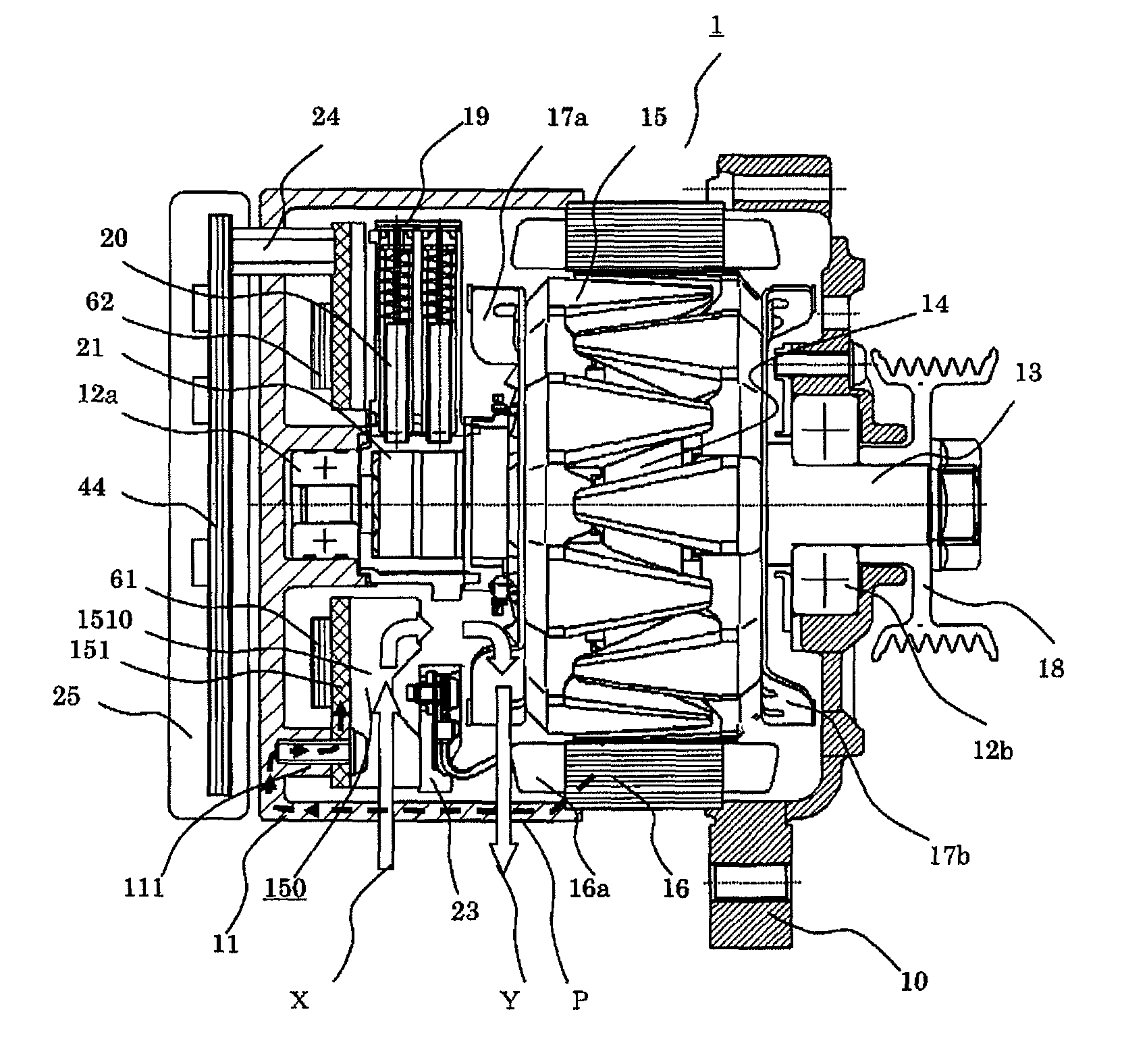
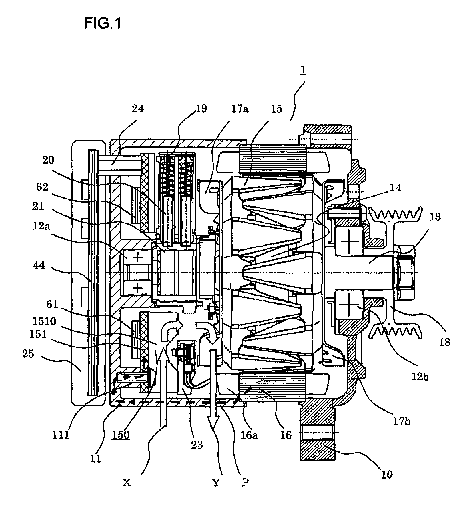
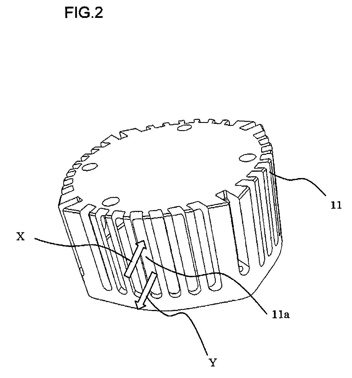
[0024]Hereinafter, an embodiment of the present invention will be described with reference to drawings. FIG. 1 is a lateral cross-sectional view showing an overall structure of an electrical rotating machine according to a first embodiment of the present invention. FIG. 2 is a perspective view of a rear bracket. FIG. 3 is a top plan view of a heat sink assembly. FIG. 4 is a bottom plan view of the heat sink assembly. FIG. 5 is a top plan view of the heat sink assembly illustrating heat movement. FIG. 6 is a plan view of a sector-shaped heat sink assembly.

[0025]In FIG. 1, an electrical rotating machine 1 includes a housing composed of a front bracket 10 and a rear bracket 11, a stator 16 having a stator winding 16a, and a rotor 15 having a shaft (rotation axis) 13 and a field winding 19. The stator 16 is arranged on the load side of the electrical rotating machine 1, and is supported by an end portion of the front bracket 10 and an end portion of the rear bracket 11. The rotor 15 is ...

second embodiment

[0038]As described above, a plurality of radiation fins 1510 arranged on the rear surface of the heat sink as shown in FIG. 4 are formed in the straight-fin shape, and extend toward the center of the radius in parallel to one another. FIG. 8 is a cross-sectional view cut along a B-B line shown in FIG. 4. When a disc-shaped heat sink 151 is subjected to thermal expansion, the heat sink 151 tends to suffer warping as indicated with a broken line shown in FIG. 8.

[0039]In this case, the fins in the straight-fin shape according to the present invention have a high section modulus against the warping toward the upward direction, the section modulus being proportional to the cube of the height of each fin. Therefore, it is possible to reduce warping caused by repetitive exposure to a high temperature and a low temperature, and to prevent the soldering from being damaged by the warping. Further, compared to a case where fins are formed in a radial-shape in which each fin extends toward the ...


PUM


Abstract

An object of the present invention is to provide an electrical rotating machine that prevents heat generated from a stator winding from being transmitted to an inverter circuit. A rotor having a field winding, and a stator having a stator winding arranged so as to surround the rotor are provided. One end of a rear bracket is connected to the stator, and arranged inside the rear bracket is a heat sink assembly including a heat sink having switching elements for controlling the field winding and the stator winding mounted thereto. The heat sink assembly is fixed to protruding portions protruding from an end surface of the rear bracket.

Description

BACKGROUND OF THE INVENTION[0001]1. Field of the Invention[0002]The present invention relates to an electrical rotating machine usable as a vehicle generator motor for use in an energy-saving automobile such as an idling stop vehicle, and more particularly to an electrical rotating machine having integrated therewith a switching circuit section for controlling a current supplied to a stator winding.[0003]2. Description of the Background[0004]As a general electrical rotating machine for use in a vehicle, a separate type in which an inverter for controlling the electrical rotating machine is mounted in a vehicle separately from the electrical rotating machine has been actually used. In the case of the separate type, a space for accommodating the inverter needs to be secured in a vehicle. In addition, a loss is caused by the length of a harness connecting the electrical rotating machine and the inverter. In order to solve these disadvantages, various types of inverter-integrated electr...

Claims


Application Information

Patent Timeline
Patent Type & Authority Patents(United States)
IPC IPC(8): H02K9/06H02K9/22H02K11/04H02K19/36
CPCH02K11/048H02K9/06H02K9/22H02K19/365H02K9/227H02K11/05
Inventor TAKECHI, ATSUSHIKIKUCHI, MASAOISODA, HITOSHIKATO, MASAKIFUJITA, MASAHIKO
Owner MITSUBISHI ELECTRIC CORP
Why Eureka
Try Eureka