Rotating electrical machine

a technology of electrical machines and rotating shafts, which is applied in the direction of dynamo-electric machines, electrical apparatus, supports/encloses/casings, etc., can solve the problems of increasing mechanical noise caused by the rotation of cooling fans, and increasing the amount of heat generated by rotating electrical machines. to achieve the effect of reducing the transmission of heat and discharging the spokes

Active Publication Date: 2020-11-17
DENSO CORP
View PDF24 Cites 0 Cited by
  • Summary
  • Abstract
  • Description
  • Claims
  • Application Information

AI Technical Summary

Benefits of technology

[0009]It is therefore an object to provide an electrical rotating machine which is designed to have an enhanced heat dissipating ability.
[0011]The electrical rotating machine, as described above, has the air inlets through which cooling air enters the housing and which is formed in the housing to cool the bearing. The spokes extend to isolate the air inlets from each other in the circumferential direction of the housing. When the stator which is located outside the spokes in the radial direction of the housing generates heat, it will cause the heat to transfer through thermal transfer paths, as defined by the spokes, to the bearing. Each of the spokes has disposed thereon one of the heat sinks each of which is equipped with the fins exposed to the air inlet, thereby achieving heat dissipation in the air inlet. In other words, the fins are exposed to a flow of cooling air entering the air inlet, thereby dissipating the from the spoke to minimize transmission of the heat to the bearing.

Problems solved by technology

Increasing an output power of the rotating electrical machine to meet such a need will result in an increase in amount of heat generated by the rotating electrical machine.
The enhancement of the cooling ability of the cooling fan, however, gives rise to a problem that mechanical noise which arises from the rotation of the cooling fan increases.
This structure, however, faces a problem that an increase in quantity of heat generated by the stator which results from the powering up of the electrical rotating machine requires the need for fine arrangement of the heat dissipating fins in order to increase a surface area of the heat dissipating fins.
The increase in surface area of the heat dissipating fins, however, results in an increase in resistance to a flow of air (i.e., cooling air) passing the heat dissipating fins, which may lead to a deterioration in cooling effects on the electrical rotating machine.
This, however, causes the electrical device to generate heat during operation of the electrical rotating machine, thereby resulting in an increase in amount of heat conducting through the case.

Method used


Image

  • Rotating electrical machine
  • Rotating electrical machine
  • Rotating electrical machine

Examples


first embodiment

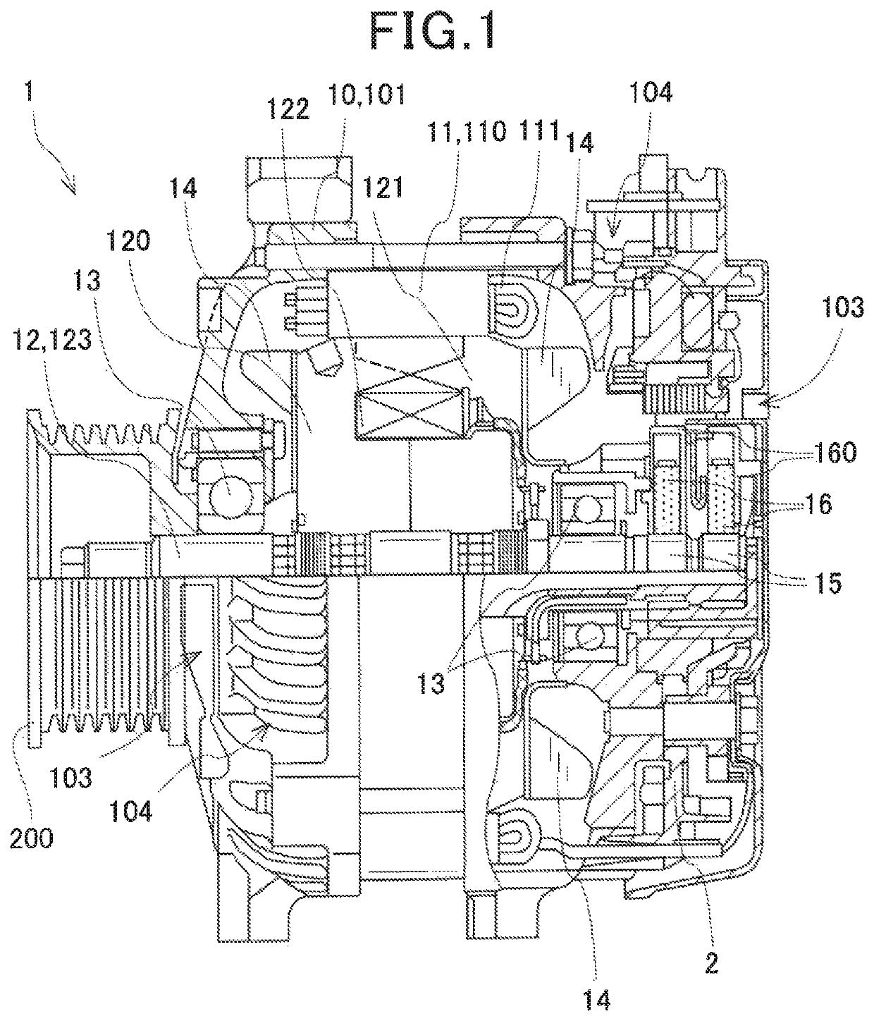
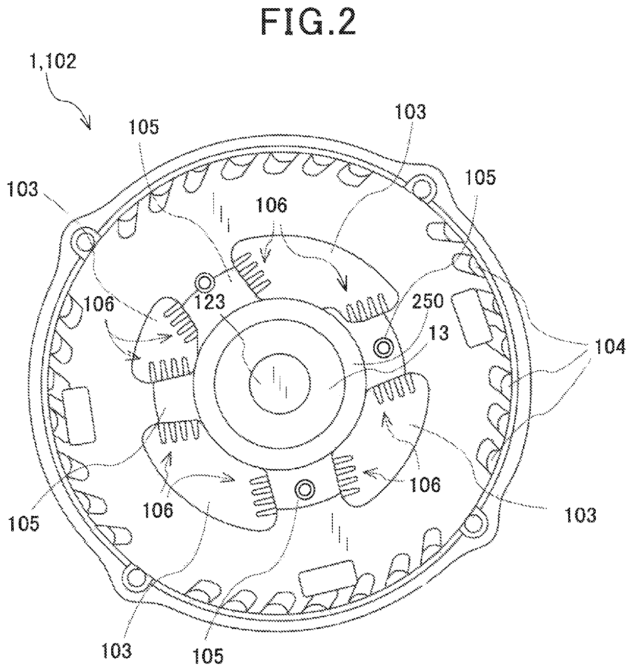
[0023]FIGS. 1 and 2 illustrate the electrical rotating machine 1 with a built-in controller according to the first embodiment. FIG. 1 is a cross section of the electrical rotating machine 1.

[0024]The electrical rotating machine 1 is mounted in an automotive vehicle and supplied with electric power from a battery to work as an electric motor which produces a drive force to move the vehicle. The electric rotating machine 1 is also supplied with a drive force (i.e., torque) generated by an engine mounted in the vehicle to work as an electrical generator to produce electric power to charge the battery. The electrical rotating machine 1 is equipped with the controller 2.

[0025]The electrical rotating machine 1 is also equipped with the housing 10, the stator 11, the rotor 12, the cooling fans 14, the slip rings 15, and the brushes 16.

[0026]The housing 10 has disposed therein the stator 11 and the rotor 12 which face each other and serves as a support which retains the rotor 12 (i.e., the ...

second embodiment

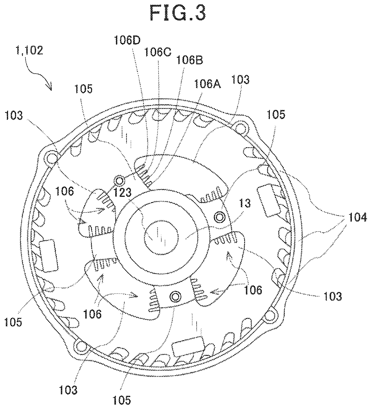
[0058]The electrical rotating machine 1 of the second embodiment is different only in structure of the heat sinks 106 from the one in the first embodiment. Other arrangements are identical, and explanation thereof in detail will be omitted here. FIG. 3 is a side view which illustrates the heat sinks 106 of the electrical rotating machine 1 in the second embodiment.

[0059]Each of the heat sinks 106 has the fins 106A, 106B, 106C, and 106D which are, as can be seen in FIG. 3, different from each other in height thereof, i.e., a distance between the tip of each of the fins 106A to 106c and the outer periphery of the spoke 105, in other words, a distance by which each of the fins 106A to 106D extend from the spoke 105. In this embodiment, the height increases stepwisely from the fin 106A which is located innermost in the radial direction of the housing 10 to the fin 106D which is located outermost side in the radial direction of the housing 10.

Beneficial Advantages of the Second Embodimen...

third embodiment

[0063]The electrical rotating machine 1 of the third embodiment is different only in structure of the heat sinks 106 from the one in the first embodiment. Other arrangements are identical, and explanation thereof in detail will be omitted here. FIG. 4 is a side view which illustrates the heat sinks 106 of the electrical rotating machine 1 in the third embodiment. FIG. 5 is a sectional view, as taken along the line V-V in FIG. 4.

[0064]Each of the heat sinks 106 is, as can be seen in FIGS. 4 and 5, disposed on a portion of a periphery of a corresponding one of the spokes 105 which does not directly face the air inlet 103. In other words, the fins 106A to 106D of each of the heat sinks 106 extend substantially parallel to each other from the spoke 105 in the axial direction of the housing 10 (i.e., the rotor 12 or the rotating shaft 123). The fins 106A to 106D are equal in projecting height to each other.

Beneficial Advantages of the Third Embodiment

[0065]The structure of the electrical...


PUM


Abstract

An electrical rotating machine includes a housing which has a bearing mounted on a wall thereof. The housing also has a plurality of air inlets, a plurality of air outlets, and spokes. The spokes extend from the bearing in a radial direction of the housing to isolate the air inlets from each other in a circumferential direction of the housing. Each of the spokes is equipped with a heat sink exposed to a flow of cooling air entering the housing through the air inlet to dissipate heat, as transmitted to the spoke, thereby minimizing transfer of the heat to the bearing through the spokes.

Description

CROSS REFERENCE TO RELATED DOCUMENT[0001]The present application claims the benefit of priority of Japanese Patent Application No. 2016-56624 filed on Mar. 22, 2016, the disclosure of which is incorporated herein by reference.BACKGROUND1. Technical Field[0002]The invention relates generally to a rotating electrical machine.2. Background Art[0003]There is an increasing need for powering up a rotating electrical machine for vehicles. Increasing an output power of the rotating electrical machine to meet such a need will result in an increase in amount of heat generated by the rotating electrical machine. In order to alleviate such a problem, improvement in cooling ability of the rotating electrical machine is being sought.[0004]The improvement of cooling ability of a cooling fan is being studied for enhancing the cooling ability of the rotating electrical machine. The cooling fan is secured to a rotating shaft of the rotating electrical machine so that it rotates following rotation of ...

Claims


Application Information

Patent Timeline
Patent Type & Authority Patents(United States)
IPC IPC(8): H02K9/02H02K5/18
CPCH02K5/18H02K9/02H02K9/06H02K5/207
Inventor KOMURA, MASATOSHISHIMA, TOMOYUKISEKIYAMA, YOSUKEKUDO, TAKUYA
Owner DENSO CORP
Why Eureka
Try Eureka