Access control system for automation equipment

a control system and automation equipment technology, applied in frequency-division multiplex, data switching networks, instruments, etc., can solve the problem that no firewall computer system can provide efficient protection, and achieve the effect of simplifying the operation, maintenance and upgrade of such a system, and increasing the security of access to automation equipmen

Active Publication Date: 2007-05-17
SCHNEIDER ELECTRIC IND SAS
View PDF5 Cites 22 Cited by
  • Summary
  • Abstract
  • Description
  • Claims
  • Application Information

AI Technical Summary

Benefits of technology

[0025] With the invention, an installation administrator can easily set up filter rules to increase security of access to automation equipment connected to the second network without any particular knowledge of computer networks or network security techniques or of technical choices about the implementation of business functions in the equipment. Rather, the filter setup can be based on functional criteria much closer to the automation business, such as the user's business / associated functional profile (accessible business functions) / target equipment type / target equipment filter profile (authorized requests). Operation, maintenance and upgrades to such a system will then be simplified, since the invention can be used without it being necessary to make any modifications to automation equipment in the installation. Moreover, the system can support a large number of different communication protocols that may or may not be based on Ethernet / IP, particularly protocols possessing an automation oriented application layer (layer 7 of the OSI model), for example of the MODBUS type (for example MODBUS on TCP / IP, MODBUS on serial link, MODBUS on CAN network).

Problems solved by technology

None of the firewall computer systems can provide efficient protection against access to a business function exposed by a target automation equipment, while only allowing the frames carrying a command and sent by an identified user with the necessary rights for execution of this command by the target equipment and while guaranteeing that any frame that does not satisfy these criteria will be systematically rejected.

Method used


Image

  • Access control system for automation equipment
  • Access control system for automation equipment

Examples


Embodiment Construction

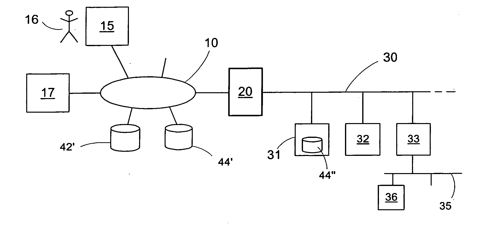
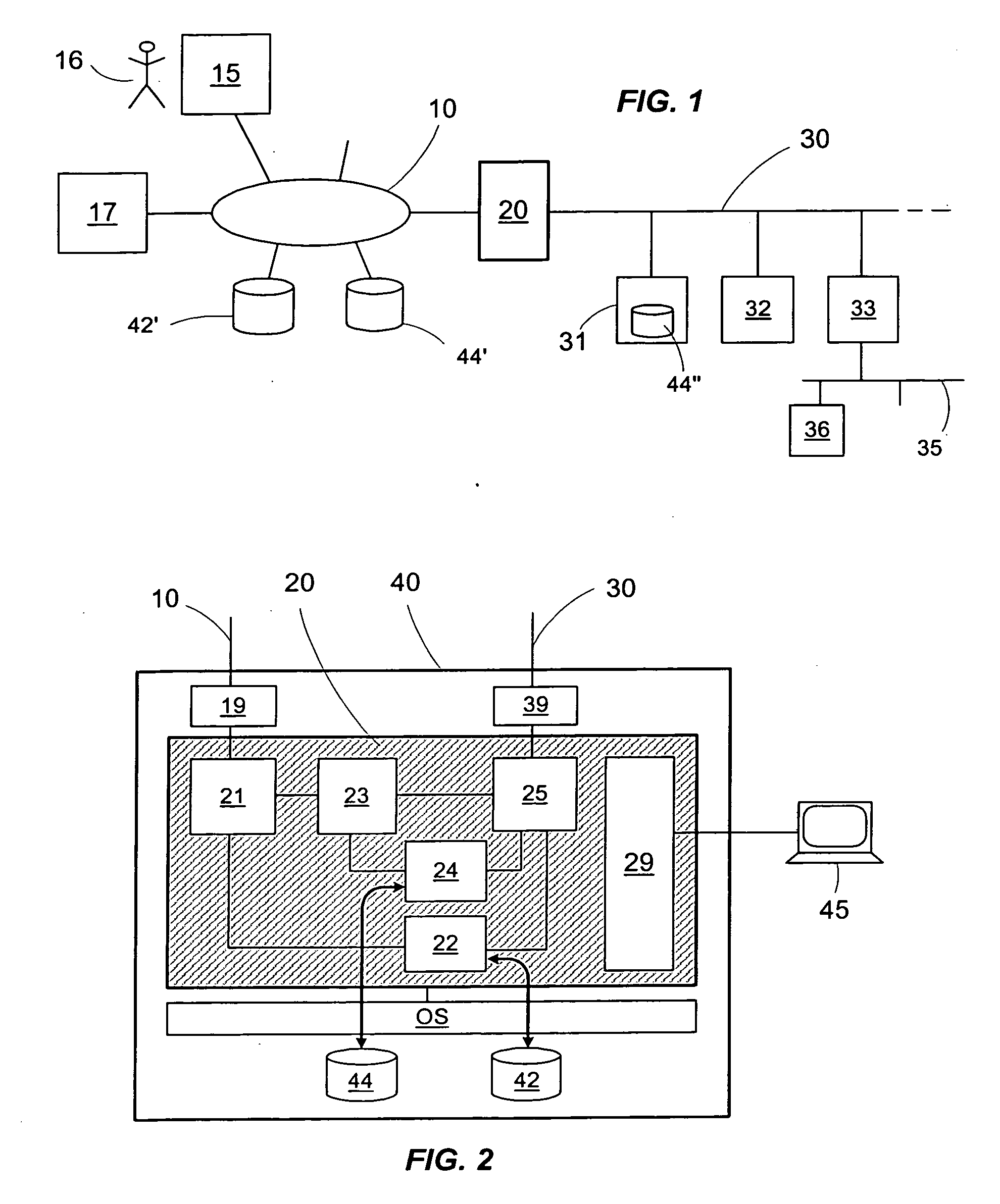
[0029] Referring now to the drawings, wherein like reference numerals designate identical, or corresponding parts throughout the several views, and more particularly to FIG. 1, the architecture in FIG. 1 shows an installation composed of several automation equipments 31,32,33 connected to a first communication network 30. In the example in FIG. 1, this first communication network 30 may be a local automation network. For example, the communication network 30 may be based on Ethernet at the OSI link layer 2 and comply with the TCP / IP standard and the UDP / IP standard, in other words an IP network. The LAN 30 may also include an OSI application layer 7 conforming to a MODBUS, UNI-TE type automation protocol, etc.

[0030] Automation equipment connected to the first network 30 may thus need to exchange information on a second communication network 10 through an access control system 20 connected both to the first network 30 and to the second communication network 10. The second network 10...


PUM


Abstract

System for controlling access to automation equipments connected to a first network, from at least one client station connected to a second network. The system includes determination means of a functional profile containing a list of business functions that a user of the client station is authorized to carry out on the equipment, analysing means of a frame sent on the second network by the user, in order to determine a request and a destination equipment, definition means of a filter profile for the destination equipment, containing, for each business function and for each protocol, a list of requests that the destination equipment is capable of receiving, and filter means capable of authorizing or prohibiting transmission of the sent frame on the first network, according to the frame, the functional profile of the identified user and the filter profile of the destination equipment.

Description

CROSS REFERENCE TO RELATED APPLICATIONS [0001] This application claims priority under 35 U.S.C. §119(e) to Provisional Application Ser. No. 60 / 473,465, filed May 28, 2003 and under 35 U.S.C. § 119(a) to French Patent Application No. 03 06459, filed May 28, 2003, the entire contents of which are incorporated herein by reference.DISCUSSION OF THE BACKGROUND [0002] 1. Field of the Invention [0003] This invention relates to a system for controlling access to one or several automation equipments connected to a first communication network, from a client station connected to a second communication network. The invention also relates to a process for controlling access to one or several automation equipments. [0004] 2. Background of the Invention [0005] The term “automation equipment” denotes, but is not limited to, any equipment for controlling, checking and / or monitoring any or all of an automation application particularly belonging to the field of industrial process automation, building ...

Claims


Application Information

Patent Timeline
Patent Type & Authority Applications(United States)
IPC IPC(8): G06F15/16
CPCH04L63/102H04L63/168
Inventor BRUN, JEAN-MICHELCHICHE, THIERRY
Owner SCHNEIDER ELECTRIC IND SAS
Why Eureka
Try Eureka