Pressure balanced spool poppet valves with printed actuator coils

a technology of actuator coils and valves, applied in the field of valves, can solve the problems of large losses of energy and system noise, high system parasitic losses, and valve types that cannot be completely pressure balanced

Inactive Publication Date: 2007-05-24
STURMAN DIGITAL SYST
View PDF21 Cites 55 Cited by
  • Summary
  • Abstract
  • Description
  • Claims
  • Application Information

AI Technical Summary

Problems solved by technology

In many applications, it is highly desirable to use a three-way valve for improved performance and control, but this is difficult due to a three-way valve's inability to pressure balance completely unless it is a spool valve, which leaks excessively.
A spool valve can create the required hydraulic paths, but while in either position (S-C or C-V) the valve has a very short leak (seal) path from a high-pressure area to a vented area, which can lead to high system parasitic losses.
This type of valve can have no leakage in either position, but when the valve is transitioning from one position to the other, there necessarily exists a direct flow path between the source and the vent that could lead to large losses of energy and system noise.
This type of valve cannot be completely pressure balanced, and therefore requires greater actuating forces than a typical pressure balanced spool valve.
The disadvantage of this system is that twice as many control valves are needed to achieve three-way control, adding system and control complexity, and further requiring more room to package.
Spool Valve: High static leakage.
Three-way hard-seat valve: High actuating force requirements (due to pressure imbalance) and short circuit loss.
However, in certain applications, the number of solenoid actuated valves preferably used may be relatively large, giving rise to quite a substantial wiring problem.
Superimposed on this in certain applications is a combination of heat and vibration that can cause premature wiring failure, and thus possibly giving rise to unsatisfactory reliability of the system.
Accordingly, wiring of the individual solenoid coils to a harness for connection to a control box would be complicated and expensive and may not have the reliability inherent in the rest of the diesel engine.

Method used


Image

  • Pressure balanced spool poppet valves with printed actuator coils
  • Pressure balanced spool poppet valves with printed actuator coils
  • Pressure balanced spool poppet valves with printed actuator coils

Examples


Embodiment Construction

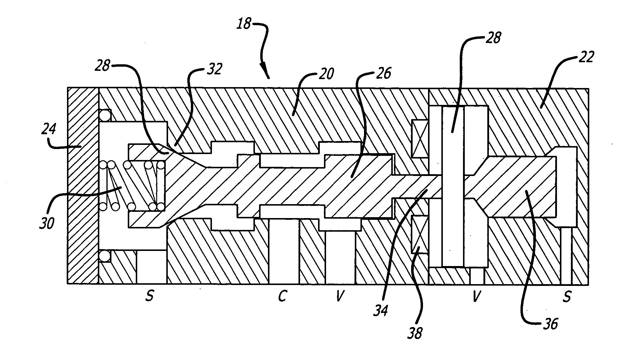
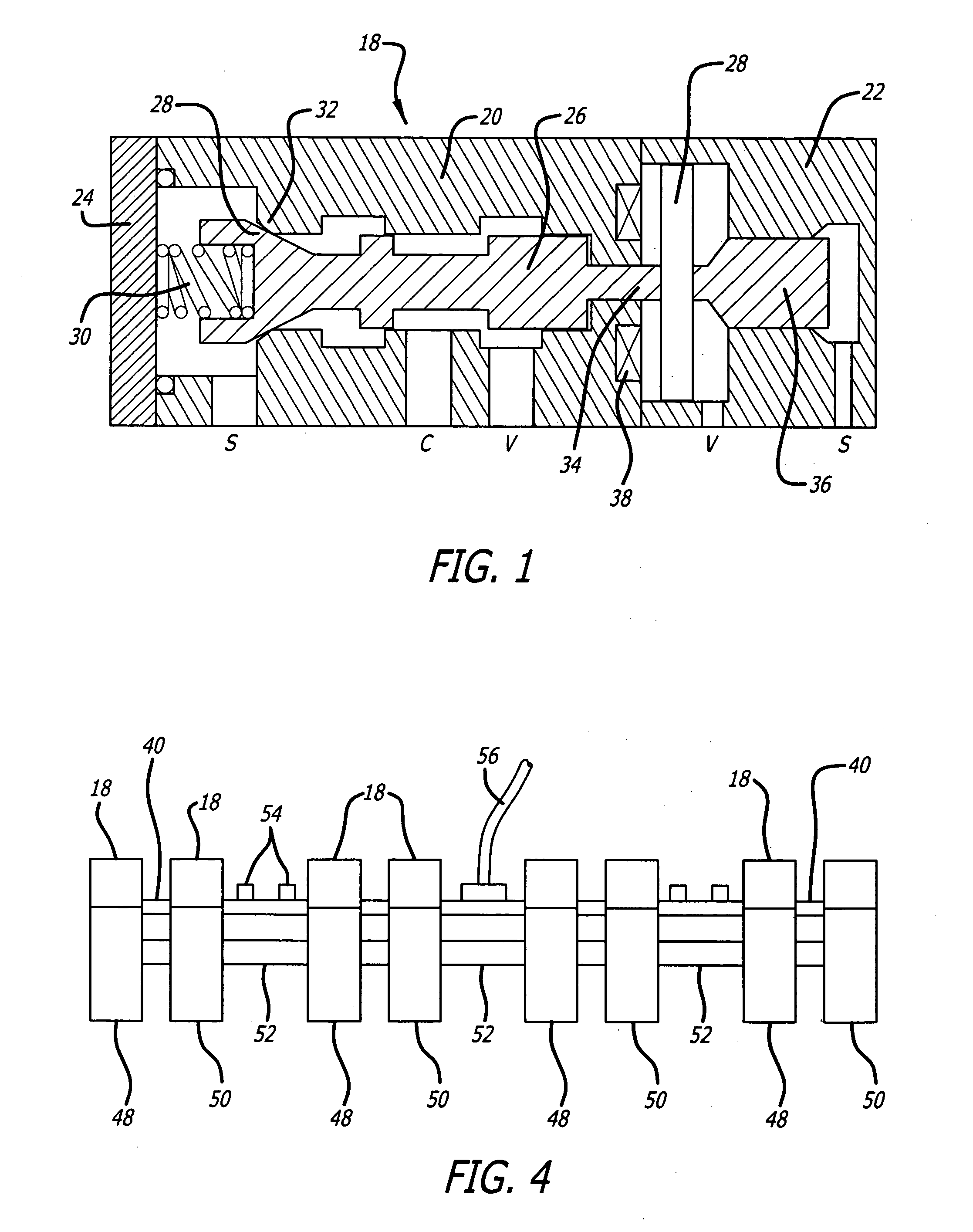
[0019] First referring to FIG. 1, a cross-section of a spool poppet valve in accordance with an embodiment of the present invention may be seen. The valve shown is a three-way valve, in that it may connect a control port C to a supply port S or to a vent port V. The valve includes a housing 20 and cap 22, both of which are of magnetic materials, and an end cap 24, which may or may not be fabricated of a magnetic material. Located within the housing 20 is a spool 26 having a poppet valve 28 at the left end thereof, with a coil spring 30 encouraging the spool and poppet valve to the right position, as shown. In this position, the control port C is coupled to the vent port V, with the poppet valve being firmly seated on seat 32 on the housing to seal the high pressure fluid in the source port S from the control port C.

[0020] At the right end of spool 26 is a magnetic armature 28 urged against end 34 of the spool by a pressure balance piston 36, the right end of which is also subjected...


PUM


Abstract

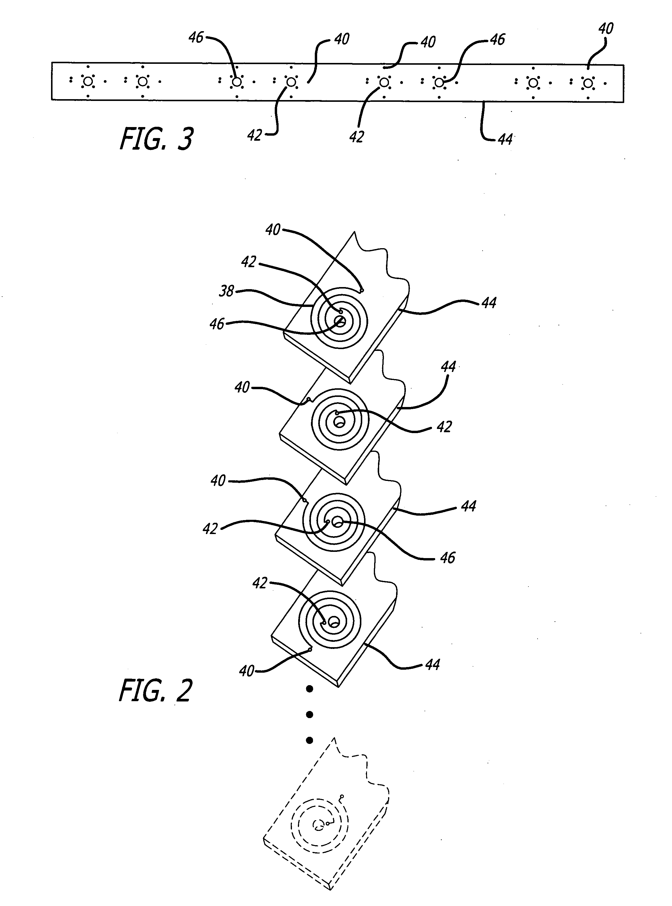
Pressure balanced spool poppet valves with printed actuator coils minimize valve leakage and facilitate efficient manufacturing and reliable operation. The spool poppet valves may be configured like a conventional spool valve, but further include a poppet valve at one end of the spool to proved much better sealing when the poppet valve is closed. Various features are disclosed, including pressure balancing for high pressure operation. The printed actuator coils for the spool poppet valves are formed by the interconnection of conductive coils on each of multiple layers of a multiple layer printed circuit board, which circuit board may have a hole there through for accommodation of mechanical and / or magnet requirements, and may include similar printed actuator coils for one or more additional spool poppet valves as well as electronic devices associated with the operation thereof. The spool poppet valves may be advantageously constructed without printed actuator coils, and the printed actuator coils may be advantageously used in actuators of other designs.

Description

CROSS-REFERENCE TO RELATED APPLICATION [0001] This application claims the benefit of U.S. Provisional Patent Application No. 60 / 738,859 filed Nov. 21, 2005.BACKGROUND OF THE INVENTION [0002] 1. Field of the Invention [0003] The present invention relates to the field of valves, and systems using a plurality of solenoid actuators. [0004] 2. Prior Art [0005] Embodiments of the present invention provide improved devices for fluid control in various applications. Typical examples include the control of a high pressure fuel injector, and hydraulic engine valve actuation systems. Two-way poppet valves (open and closed) are often used due to their low leakage characteristics. In many applications, it is highly desirable to use a three-way valve for improved performance and control, but this is difficult due to a three-way valve's inability to pressure balance completely unless it is a spool valve, which leaks excessively. For purposes of this disclosure, a three-way valve will be described ...

Claims


Application Information

Patent Timeline
Patent Type & Authority Applications(United States)
IPC IPC(8): F15B13/044
CPCF15B13/0402F15B13/044F16K11/02F16K31/0613H01F5/003Y10T137/86622
Inventor STURMAN, ODED EDDIEMASSEY, STEVEN E.
Owner STURMAN DIGITAL SYST
Why Eureka
Try Eureka