Bearing with ic tag and seal for the same

a technology of bearing devices and seals, applied in the field of bearing devices, can solve the problems of inability to identify individual bearing devices, unable to achieve individual identification of bearing devices, and unable to meet the requirements of individual identification

Inactive Publication Date: 2007-05-24
NTN CORP
View PDF15 Cites 12 Cited by
  • Summary
  • Abstract
  • Description
  • Claims
  • Application Information

AI Technical Summary

Benefits of technology

[0012] In the case of the non-contact type metallic sealing member, the sealing member is fitted to one of the raceway members, which it is to be fitted to, in metal-to-metal contact fashion and, therefore, if the antenna-equipped IC tag is fitted directly to the non-contact type sealing member, a problem would arise in difficulty reading information because of absorption of radio waves. However, when the antenna-equipped IC tag is fitted through the insulating piece such as achieved in the present invention, information reading from the IC tag can be accomplished satisfactorily without accompanying difficulty resulting from absorption of radio waves in the raceway members.

Problems solved by technology

However, the contents that can be born in the bearing device and / or the package thereof are limited to the minimum.
However, the bearing identification information represented by the numbering conventionally marked in the packages containing bearing devices has a problem in that it tends to be lost or become illegible after the bearing device has been assembled.
The markings made in the respective bearing devices contain so small an amount of information marked, that individual identification of those bearing devices may not be possible to achieve.
However, since the RFID-based IC tag makes use of microwaves, mounting of the RFID-based IC tag on a bearing device makes it impossible for the RFID-based IC tag to be read out because during the information reading raceway members of the bearing device absorbs the microwaves.
In other words, if the IC tag having an antenna was mounted directly on an inner race or an outer race of the bearing device, troubles occur as a result of the microwaves being absorbed in the inner and outer race of the bearing device, which are made of metal other than the antenna, and / or other metallic members such as, for example, a bearing housing when the bearing device is incorporated in a real machine.
For this reason, it often occurs that difficulty is encountered in reading the information recorded on the IC tag.
Although the IC tag itself is available, which is so designed as to be affixed directly to metallic components, such tag is expensive and bulky.
Also, the bearing devices are varying in size (small or large) and thickness (thin or thick) and have a limited space for accommodating the respective IC tag.
As the RFID-based IC tag, the RFID-based IC tag disclosed in the Japanese patent publication referred to above makes use of a spirally coiled antenna as an antenna and, therefore, cannot be designed to have a reduced size in a widthwise direction thereof.
Although IC tags, including an antenna, designed to be ultra small in size have been suggested, those IC tags have some performance factors such as, for example, information recording capacity sacrificed in the face of compactization and, therefore, it is quite often experienced that a desired amount of information cannot be recorded.

Method used


Image

  • Bearing with ic tag and seal for the same
  • Bearing with ic tag and seal for the same
  • Bearing with ic tag and seal for the same

Examples


first embodiment

[0029] FIGS. 4 to 6 illustrates a second preferred embodiment of the present invention. The IC-tagged bearing device shown therein is similar to that shown in and described with reference to FIGS. 1 to 3 in connection with the first embodiment, but differ therefrom in that in place of the contact type sealing member 5 used in the bearing device according to the previously described embodiment, a non-contact type sealing member 5A made of metallic material is employed. This non-contact type sealing member 5A is in the form of a press-worked metallic member such as, for example, steel plate shaped by the use of a press work and is often referred to as a shield. In this embodiment, the antenna-equipped IC tag 9A is secured to this electroconductive sealing member 5A through an electrically insulating piece 21. The IC tag 9A employed therein is secured in this manner to one of opposite surfaces of the sealing member 5A that confronts outwardly of the bearing device. The electrically ins...

second embodiment

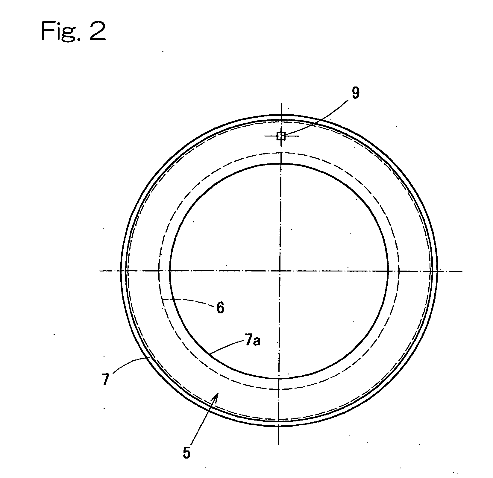
[0033] According to the foregoing second embodiment, since the antenna-equipped IC tag 9A is fitted through the electrically insulating piece 21, reading of the information from the IC tag 9A can be accomplished satisfactorily without absorption of radio waves taking place from, for example, any of the inner and outer races 1 and 2.

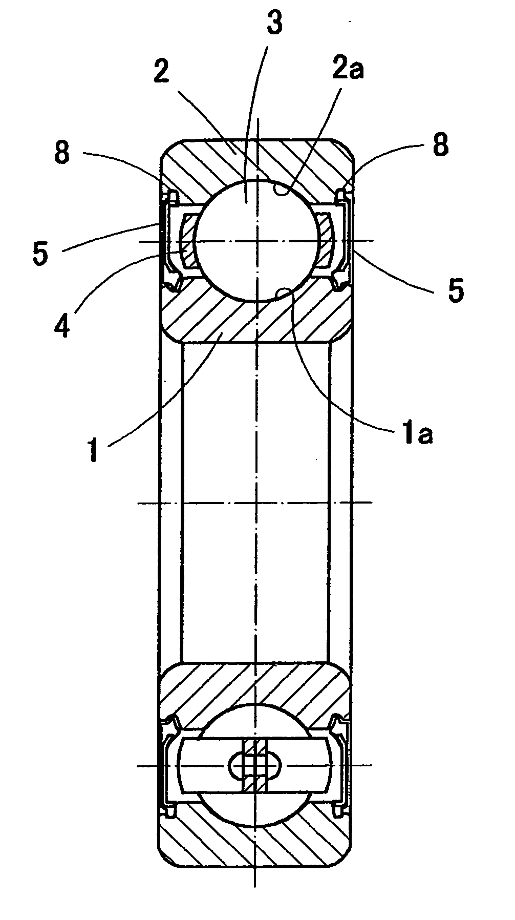
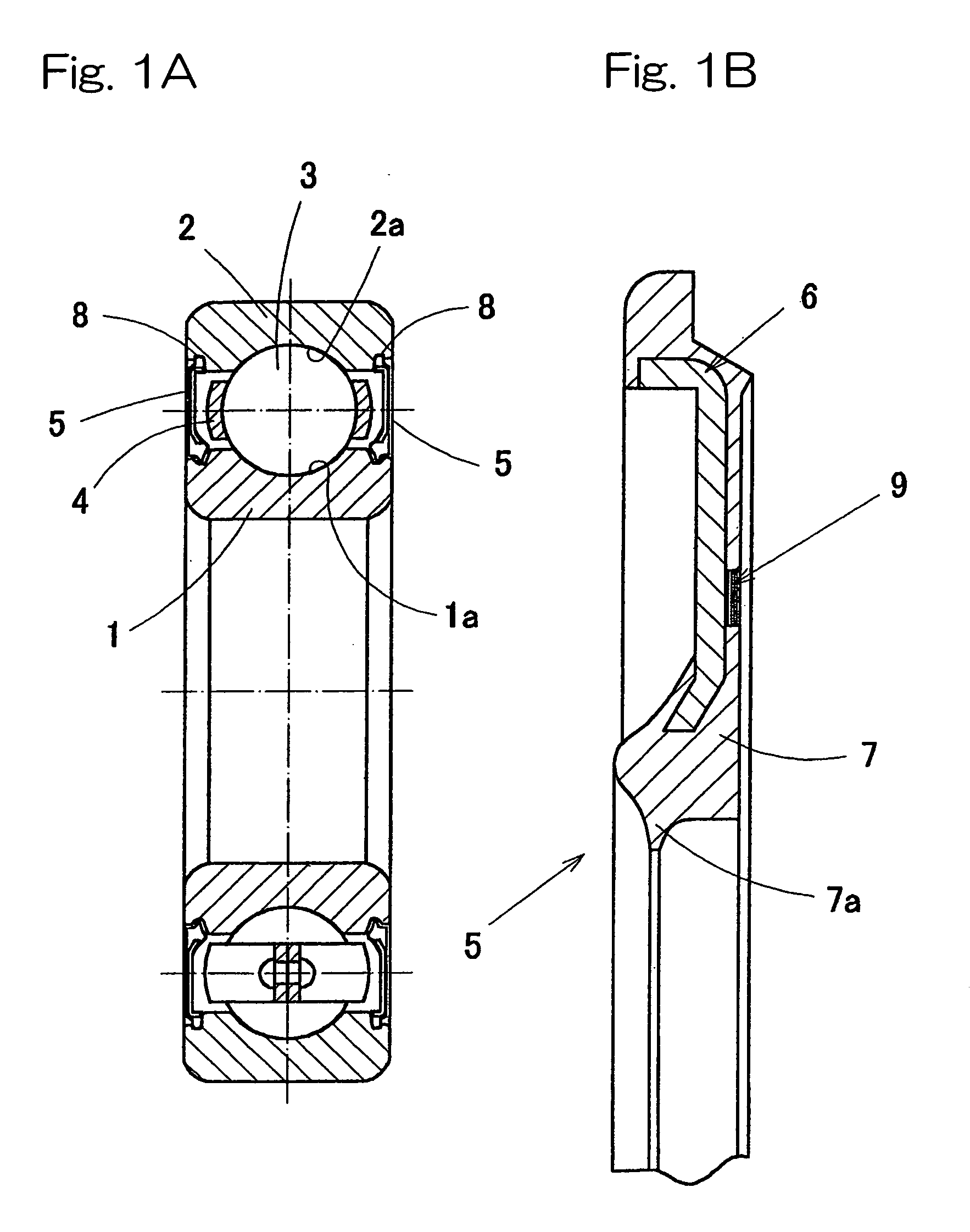
[0034] Although in describing any of the first and second embodiments of the present invention, reference has been made to the deep groove ball bearing, the present invention can be equally applied to any type of bearing equipped with the sealing member. By way of example, the present invention is equally applicable to a radial bearing such as, for example, a cylindrical roller bearing, a tapered roller bearing, self-aligning bearing, angular contact ball bearing and center bearing and also to a thrust bearing. Also, the present invention is equally applicable to any other special bearing such as, for example, a wheel support bearing for cars and for any ...


PUM


Abstract

To provide an IC-tagged bearing device, in which difficulties brought about by reflection and/or absorption of radio waves upon and/or in raceway members or the like can be avoided, information recording can be accomplished satisfactorily, an IC tag itself does not require an antenna, and the IC tag can have a compact, yet large capacity. The bearing device, having a bearing space delimited between inner and outer races (1, 2) and sealed by a sealing member (5), includes an IC tag (9) which utilizes a core metal (6) as an antenna and which is fitted to the sealing member (5). The sealing member (5) is made of a rubber material or a synthetic resin having the core metal (6).

Description

FIELD OF THE INVENTION [0001] The present invention relates to a bearing device having incorporated therein an IC tag capable of performing communication on a non-contact basis and a sealing member therefor. BACKGROUND ART [0002] It has hitherto been a general practice for the bearing device to have the model number, precision code, special requirement code and manufacturing lot number marked in the product itself or printed in a package thereof. However, the contents that can be born in the bearing device and / or the package thereof are limited to the minimum. [0003] As IC tags which are affixed to various products and which are compact in size and capable of recording a large amount of information therein, various IC tags for use in radio frequency identification (RFID) have hitherto been developed, which utilizes the RFID technology. (See, for example, the Japanese Laid-open Patent Publication No. 2002-298116.) [0004] However, the bearing identification information represented by ...

Claims


Application Information

Patent Timeline
Patent Type & Authority Applications(United States)
IPC IPC(8): G08B13/14F16C19/00F16C19/52F16C33/78F16C41/00G06K19/077
CPCF16C33/00F16C33/7853F16C41/008G06K19/07745G06K19/07749F16C19/06H01L2924/0002H01L2924/00F16J15/3296F16C33/7816F16C41/007
Inventor SERIU, MAKOTOTAKADA, SEIICHI
Owner NTN CORP
Why Eureka
Try Eureka