Liquid crystal display and manufacturing method therefor

a technology of liquid crystal display and manufacturing method, which is applied in the field of liquid crystal display, can solve the problems of complicated method, limited lifespan of rubbing cloth, and needing frequent replacemen

Active Publication Date: 2007-05-24
TSINGHUA UNIV +1
View PDF2 Cites 37 Cited by
  • Summary
  • Abstract
  • Description
  • Claims
  • Application Information

AI Technical Summary

Problems solved by technology

However, some drawbacks arise from a mechanical contact of the rubbing cloth with the surface of the alignment material.
This method is complicated because a baking process of the polyimide layer takes long time, and the rubbing int...

Method used


Image

  • Liquid crystal display and manufacturing method therefor
  • Liquid crystal display and manufacturing method therefor
  • Liquid crystal display and manufacturing method therefor

Examples


Embodiment Construction

[0018] Reference will now be made to the drawings to describe preferred embodiment of the LCD and its manufacturing method, in detail.

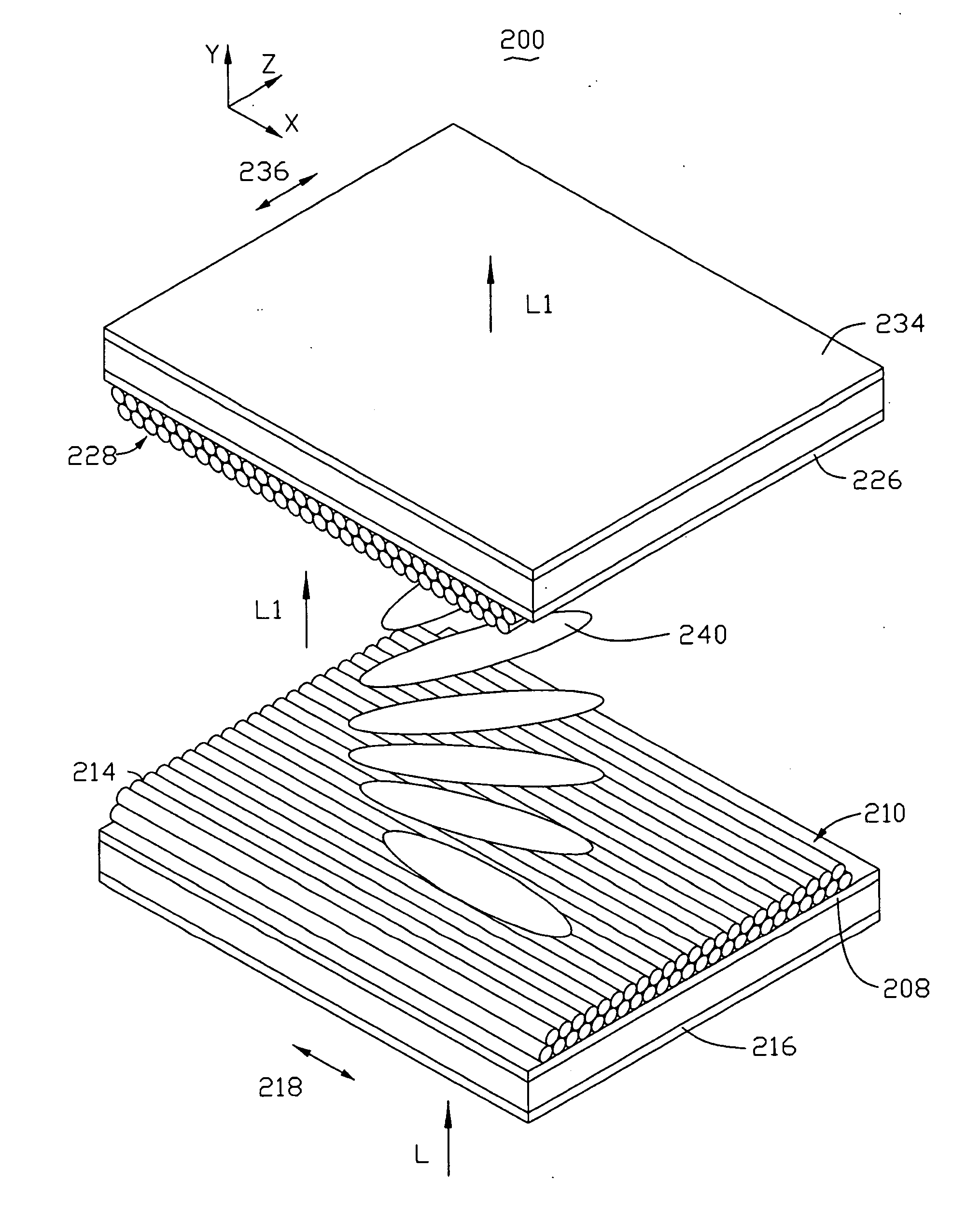
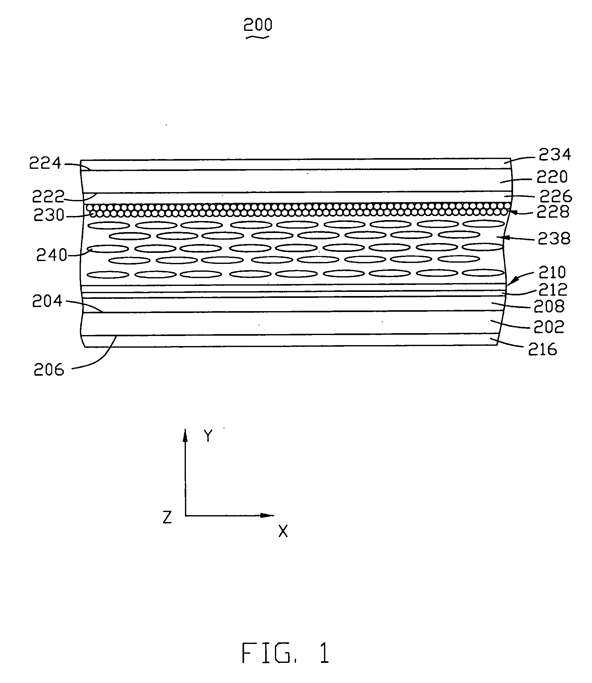
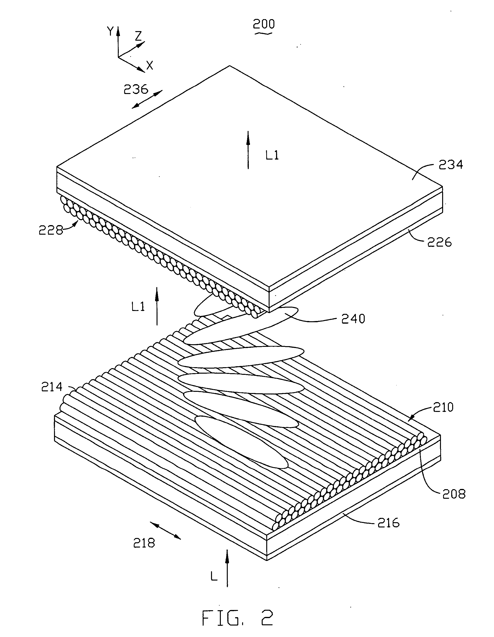
[0019] Referring to FIG. 1, an LCD 200 in accordance with a preferred embodiment is shown. The LCD 200 mainly includes a first base plate 202, a second base plate 220, and a liquid crystal layer 238.

[0020] The first base plate 202 is opposite to the second base plate 220. The liquid crystal layer 238 includes a plurality of rod-like liquid crystal molecules 240 and is located between the two base plates 202 and 220. A first transparent electrode layer 208 and a first thin film of carbon nanotubes 210 are positioned on an inner surface 204 of the first base plate 202 in that order. A first polarizer 216 is positioned on an outer surface 206 of the first base plate 202. A second transparent electrode layer 226 and a second thin film of carbon nanotubes 228 are positioned on an inner surface 222 of the second base plate 220 in that order. A second pola...


PUM


Abstract

A liquid crystal display (200) includes a first base plate (202), a second base plate (220), a liquid crystal layer (238) located between the first base plate and the second base plate, and two alignment films (210, 228). The two alignment films are respectively positioned on inner surfaces of the first base plate and the second base plate. Each alignment film is a film of oriented carbon nanotubes (212, 230). An oriented direction of the carbon nanotubes on the first base plate is perpendicular to that of the carbon nanotubes on the second base plate. A manufacturing method for the liquid crystal display is also disclosed.

Description

BACKGROUND [0001] 1. Technical Field [0002] The present invention relates to liquid crystal displays (LCDs) and manufacturing methods for the LCDs and, more particularly, to an LCD with alignment films and a manufacturing method for the LCD. [0003] 2. Description of the Related Art [0004] Because LCDs have the advantages of portability, low power consumption, and low radiation, they have been widely used in various portable information products such as notebooks, personal digital assistants (PDAs), video cameras, and the like. Furthermore, LCDs are considered to have the potential to completely replace cathode ray tube (CRT) monitors and televisions. [0005] Referring to FIG. 4, a conventional LCD 100 generally includes a first base plate 102, a second base plate 110, and a liquid crystal layer 118 located between the two base plates 102 and 110. An alignment layer 106 is formed on an inner surface 104 of the first base plate 102. An alignment layer 114 is formed on an inner surface ...

Claims


Application Information

Patent Timeline
IPC IPC(8): G02F1/1337
CPCB82Y20/00G02F1/1337G02F2001/133765G02F2202/36G02F1/133765Y10S977/742Y10S977/755Y10S977/932
Inventor LIU, LIANGJIANG, KAI-LIFAN, SHOU-SHAN
Owner TSINGHUA UNIV
Why Eureka
Try Eureka