Passive cooling for fiber to the premise (FTTP) electronics

a technology of fiber to the premise and electronics, applied in the direction of cooling/ventilation/heating modification, lighting and heating apparatus, electrical equipment, etc., can solve the problems of increasing the heat generated by electronics, fan maintenance, and electrical equipment generating significant amounts of hea

Inactive Publication Date: 2007-05-24
TELLABS BEDFORD
View PDF26 Cites 117 Cited by
  • Summary
  • Abstract
  • Description
  • Claims
  • Application Information

AI Technical Summary

Problems solved by technology

Electronics generate significant amounts of heat, which may be compounded by external thermal loading such as in situations where the electronics are operating within enclosures subject to solar loading.
This approach is inadequate for electronics supporting higher data rate architectures (e.g., Very high speed Digital Subscriber Line (VDSL)), which increas

Method used


Image

  • Passive cooling for fiber to the premise (FTTP) electronics
  • Passive cooling for fiber to the premise (FTTP) electronics
  • Passive cooling for fiber to the premise (FTTP) electronics

Examples


Embodiment Construction

[0018] A description of preferred embodiments of the invention follows.

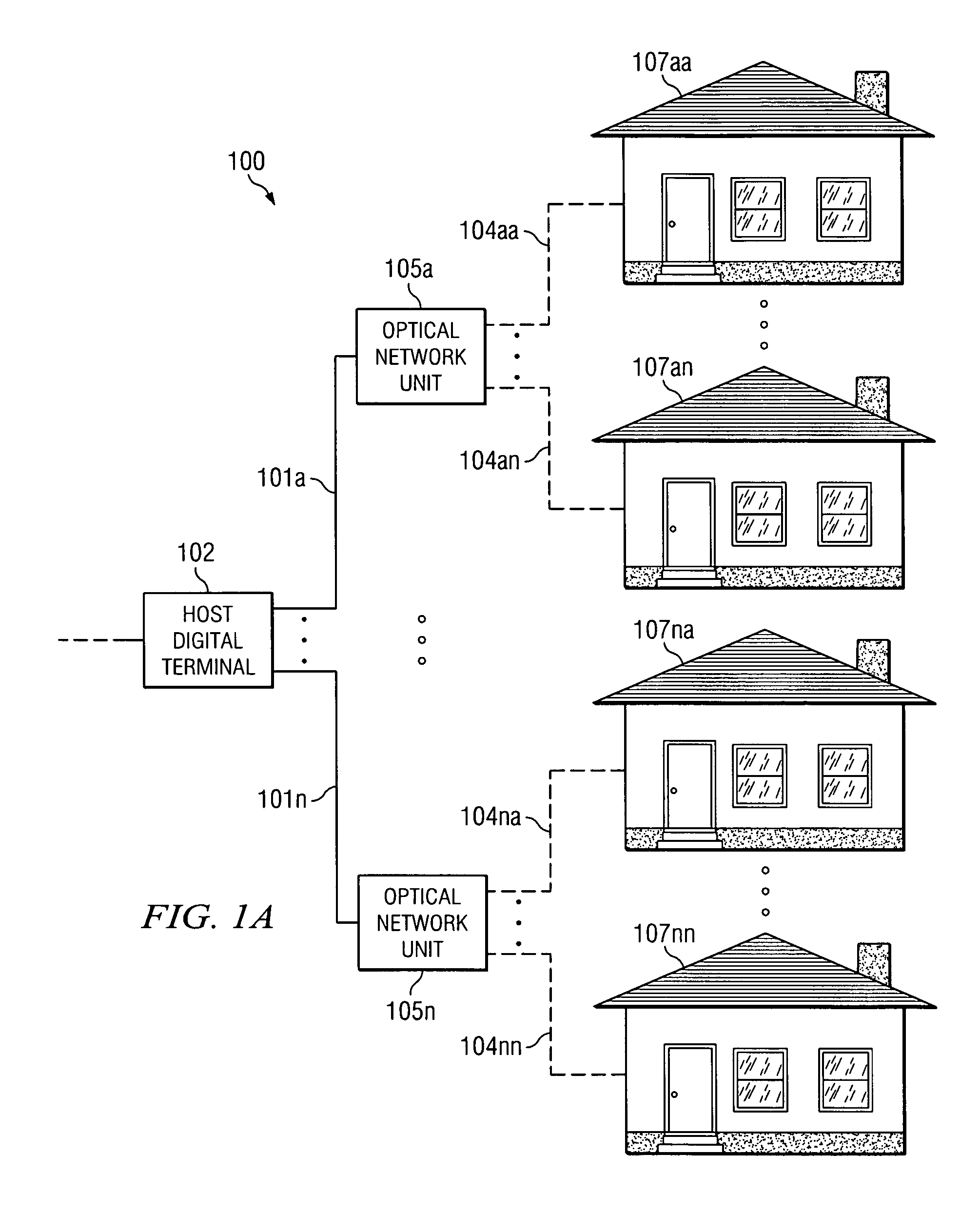
[0019]FIG. 1A is an example optical network architecture 100 referred to as a Fiber To The Curb (FTTC) architecture in which an embodiment of the present invention may be employed. A Host Digital Terminal (HDT) 102 communicates via optical fiber links 101a-101n with multiple Optical Network Units (ONUs) 105a-105n. The ONUs 105a-105n in turn communicate via copper links 104aa-104nn (e.g., twisted pair) with subscribers 107aa-107nn.

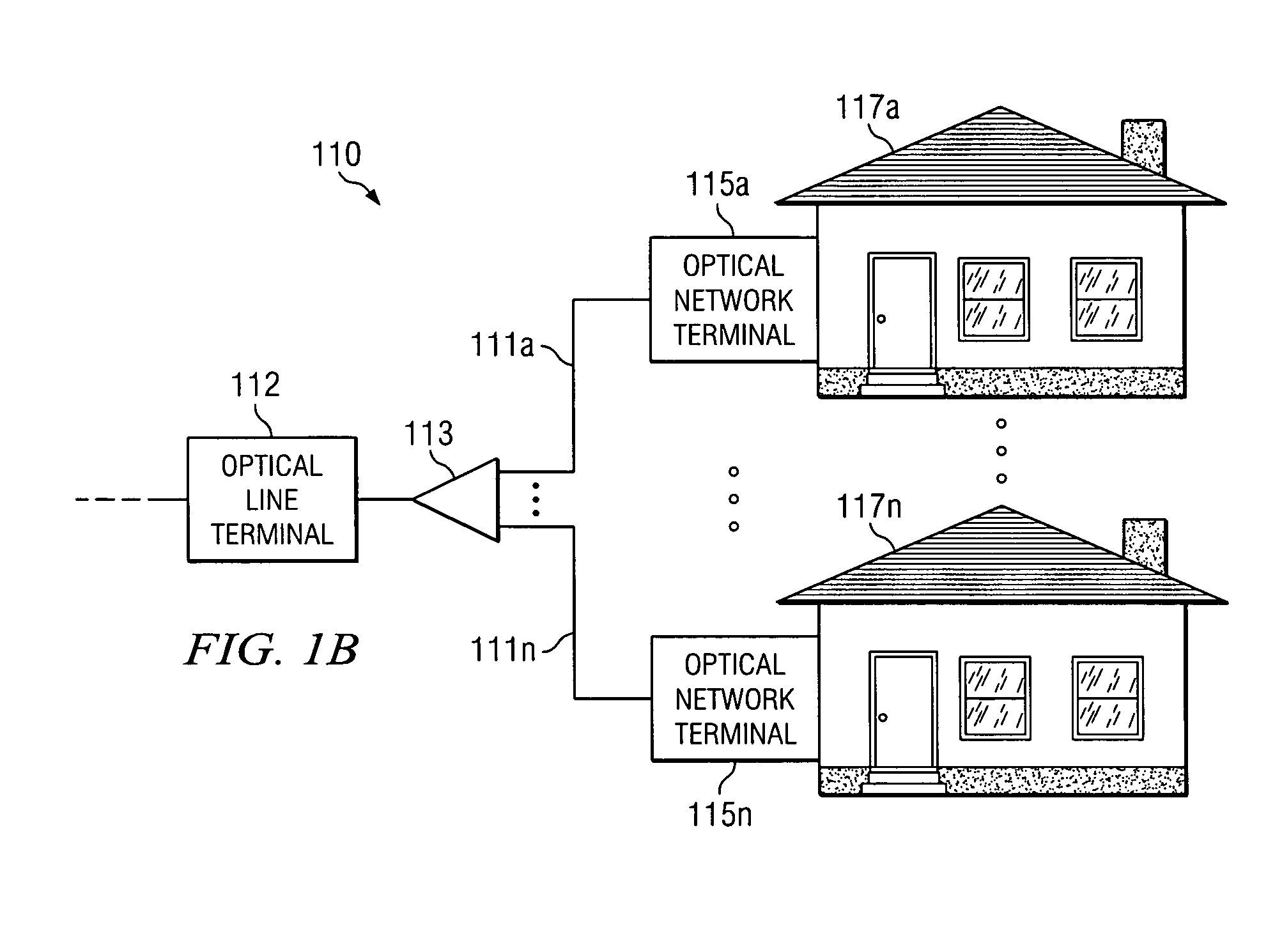
[0020]FIG. 1B is another example optical network architecture 110 referred to as the Fiber To The Premise (FTTP) architecture (e.g., Fiber To The Business (FTTB) or Fiber To The Home (FTTH)) in which an embodiment of the present invention may be employed. An Optical Line Terminal (OLT) 112 communicates via an optical splitter 113 and optical fiber links 111a-111n with Optical Network Terminals (ONTs) 115a-115n associated with subscribers 117a-117n. The OLT 112 and HDT 102 may be connec...


PUM


Abstract

A phase change material, including multiple phase change materials of different formulations, is placed in heat transfer association with an electronics enclosure (e.g., a sealed enclosure) deployed in an environment that causes the electronics and the phase change material to experience periods of heating and periods of cooling. During the periods of heating, the phase change material absorbs heat and changes at least partially from a first state to a second state to maintain the temperature of the electronics at a desirable level. During the periods of cooling, the phase change material reverts at least partially back to the first state for future heat absorption. The phase change material is cooled by a thermally cooler body such as the night sky. The electronics enclosure and phase change material may be placed in a second enclosure covered with a paint having a paint additive that reflects solar radiation.

Description

BACKGROUND OF THE INVENTION [0001] Electronics generate significant amounts of heat, which may be compounded by external thermal loading such as in situations where the electronics are operating within enclosures subject to solar loading. The electronics may be equipped with heat sinks to cool the electronics under such operating conditions. This approach is inadequate for electronics supporting higher data rate architectures (e.g., Very high speed Digital Subscriber Line (VDSL)), which increase the heat generated by the electronics. [0002] Traditionally, mechanical fans directing airflow across electronics have been used for the electronics that generate greater amounts of heat when the heat sinks do not suffice. However, fans have several disadvantages. First and foremost, fans require maintenance. In some cases, the electronics include additional software processes to detect and provide an alarm signal for fan failure. When a fan fails, the electronics may have to be shut down un...

Claims


Application Information

Patent Timeline
IPC IPC(8): H05K7/20
CPCH05K7/20
Inventor LOW, ANDREW G.RAMACHANDRAN, THYAGARAJAN
Owner TELLABS BEDFORD
Why Eureka
Try Eureka