Transmission time difference measurement method and system

a technology of transmission time difference and measurement method, applied in the field of mobile communication, can solve the problems of a plurality of lmus to be newly installed, hardware that can receive gps signals must be mounted in a base station,

Inactive Publication Date: 2007-05-24
NEC CORP
View PDF5 Cites 83 Cited by
  • Summary
  • Abstract
  • Description
  • Claims
  • Application Information

AI Technical Summary

Benefits of technology

[0081] It is an object of the present invention to provide a technology that allows the measurement of transmission timing differe

Problems solved by technology

However, because base stations do not operate in synchronization in a W-CDMA network, the transmission timing of pilot signals does not coincide.
However, in the RTD measurement method that uses GPS times that is established by the 3GPP standardization document TS 25.301, the pr

Method used


Image

  • Transmission time difference measurement method and system
  • Transmission time difference measurement method and system
  • Transmission time difference measurement method and system

Examples


first working example

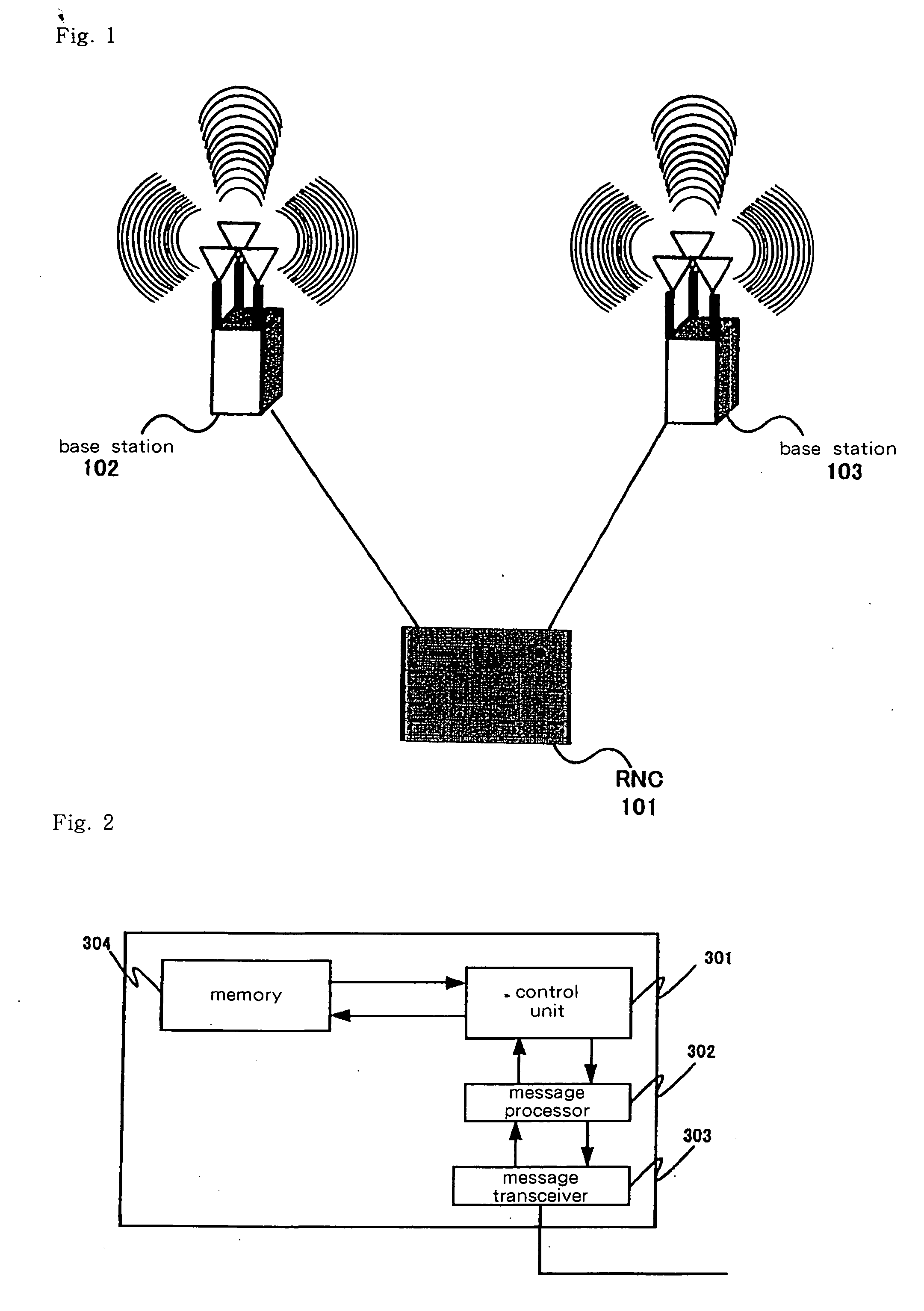
[0116]FIG. 11 shows the configuration of the transmission time difference measurement system in the first working example of the present invention.

[0117] The transmission time difference measurement system shown in FIG. 11 is made up from: RNC 1301, base stations 1302 and 1303, and terminal 1304.

[0118] RNC 1301 uses messages to control base stations 1302 and 1303.

[0119] Base stations 1302 and 1303 exchange radio signals with terminal 1304.

[0120] Terminal 1304 establishes a connection with RNC 1301 and is controlled by RNC 1301 through the transmission and reception of messages with RNC 1301.

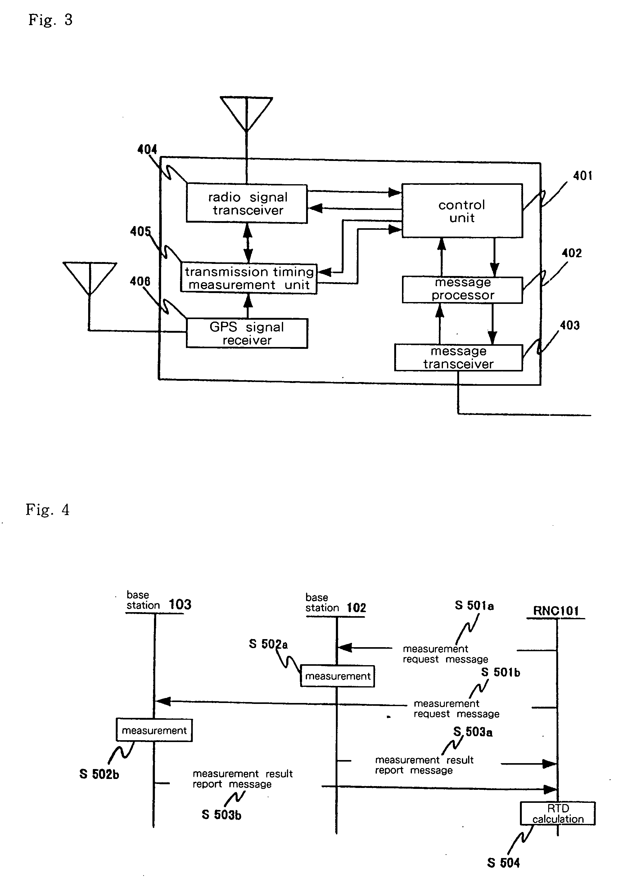
[0121]FIG. 12 shows the configuration of base stations 1302 and 1303 in the first working example of the present invention. FIG. 12 shows only those portions necessary for the explanation.

[0122] Base stations 1302 and 1303 shown in FIG. 12 are made up from: control unit 1401, message processor 1402, message transceiver 1403, radio signal transceiver 1404, and radio signal transmission / recep...

second working example

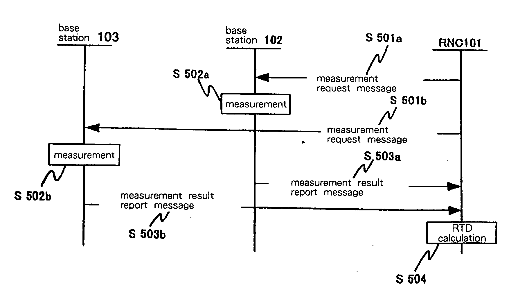
[0177] In the first working example, the terminal that carried out soft hand-over by necessity also performed the measurements that were required for calculating RTD, but a method may also be considered in which the necessary measurements are carried out by only specific terminals and not all terminals that carry out soft hand-over. This method will be referred to as the second working example and is explained below with reference to FIG. 16.

[0178]FIG. 16 is a view for explaining the sequence of the transmission time difference measurement method in the second working example of the present invention. The sequence from Step 1701 to Step 1709 is identical to that of the first working example, and explanation is therefore here omitted. In addition, in the present working example, information indicating the functions of terminal 1304, specifically, the physical capacity and measurement accuracy that can be attained by terminal 1304, are stored in memory 304 of RNC 1301. Explanation re...

third working example

[0182] In the second working example of the present invention, explanation regarded a method for selecting a terminal that carries out measurements using as a standard the capabilities possessed by the terminal, but a method may also be considered in which a terminal is selected based on the number of measurements that are carried out within a fixed time interval. This method will be described as the third working example while referring to FIG. 16. The sequence of Steps 1701 to 1709 is identical to the first working example, and explanation regarding these steps is therefore here omitted.

[0183] In Step 1801, upon verifying the completion of the changes of settings in terminal 1304, control unit 301 of RNC 1301 refers to RTD information that is stored in memory 304 and acquires the number of measurements for the RTD calculation that are carried out by terminal 1304 within a predetermined time interval.

[0184] If the number of measurements that terminal 1304 carries out within a pre...


PUM


Abstract

The propagation time (1605) of signals between a terminal (1304) and a base station (1302) is calculated from the round-trip time (1601) of signals between the terminal (1304) and the base station (1302) and the turn-around time (1603) from the reception by terminal (1304) of a signal from base station (1302) until the transmission of the signal to the base station (1302). The propagation time (1606) of signals between the terminal (1304) and another base station (1303) is similarly calculated. The difference between the propagation times (1605 and 1606) and the arrival time difference (1607) that is calculated in the terminal (1304) are then compared to calculate the transmission time difference (1608) between the base stations (1302 and 1303).

Description

TECHNICAL FIELD [0001] The present invention relates to a transmission time difference measurement method and system in the field of mobile communication, and more particularly to a transmission time difference measurement method and system for measuring the differences in transmission times among base stations when determining the geographical location of a mobile station in a mobile communication network. BACKGROUND ART [0002] In recent years, a multiplicity of methods have been reported as methods of specifying the position of portable telephone terminals (hereinbelow referred to as “terminals”). A number of standardization organizations are standardizing positioning methods and positioning sequences for specifying the positions of terminals. [0003] The Third General Partnership Project (hereinbelow abbreviated as “3GPP”), which is one of the organizations implementing standardization and that has established the standards for W-CDMA, is proceeding with the standardization of pos...

Claims


Application Information

Patent Timeline
IPC IPC(8): H04J1/16H04J3/06G01S5/12G01S5/14G01S19/12G01S19/48H04L7/00H04W24/00H04W64/00
CPCG01S5/021H04W56/006H04W56/0065
Inventor MATSUDA, JUNICHIKURASHIMA, AKIHISA
Owner NEC CORP
Why Eureka
Try Eureka