
Method and apparatus for decoding DTMF tones

a technology of dtmf and tones, applied in electrical equipment, manual exchanges, substation equipment, etc., can solve the problems of difficult synchronization and timing, cost of non-standard cycle length, and inability to detect and recognize dtmf with satisfactory precision, and achieve accurate decoding of dtmf data

Active Publication Date: 2007-05-24
ADEMCO INC
View PDF4 Cites 9 Cited by
  • Summary
  • Abstract
  • Description
  • Claims
  • Application Information

AI Technical Summary

Benefits of technology

[0008] It is an object to the present invention to provide apparatus and method which will accurately decode DTMF data.
[0009] A further object of the present invention is to utilize in apparatus and method which will preserve the amplitude of the original signals and thus permit additional signal analysis.
[0010] Another object of the present invention is to provide apparatus and method which will be less expensive than approach is used heretofore.
[0011] Still another object of the invention is to provide an inexpensive zero-crossing detector.
[0012] Yet another object of the invention is to reduce the cost of security panels.

Problems solved by technology

For shorter lengths, synchronization and timing are more difficult.
However, getting the correct frequencies often requires usage of a suitable crystal for the processor itself—at the cost of non-standard cycle length, etc.
It is not easy to detect and recognize DTMF with satisfactory precision.
It is rather complicated, so it is used only marginally.
The relatively expensive DTMF decoding chip or a DSP with a costly A / D converter constitutes a material part of the total cost of the security panel.

Method used


Image

  • Method and apparatus for decoding DTMF tones
  • Method and apparatus for decoding DTMF tones
  • Method and apparatus for decoding DTMF tones

Examples


Embodiment Construction

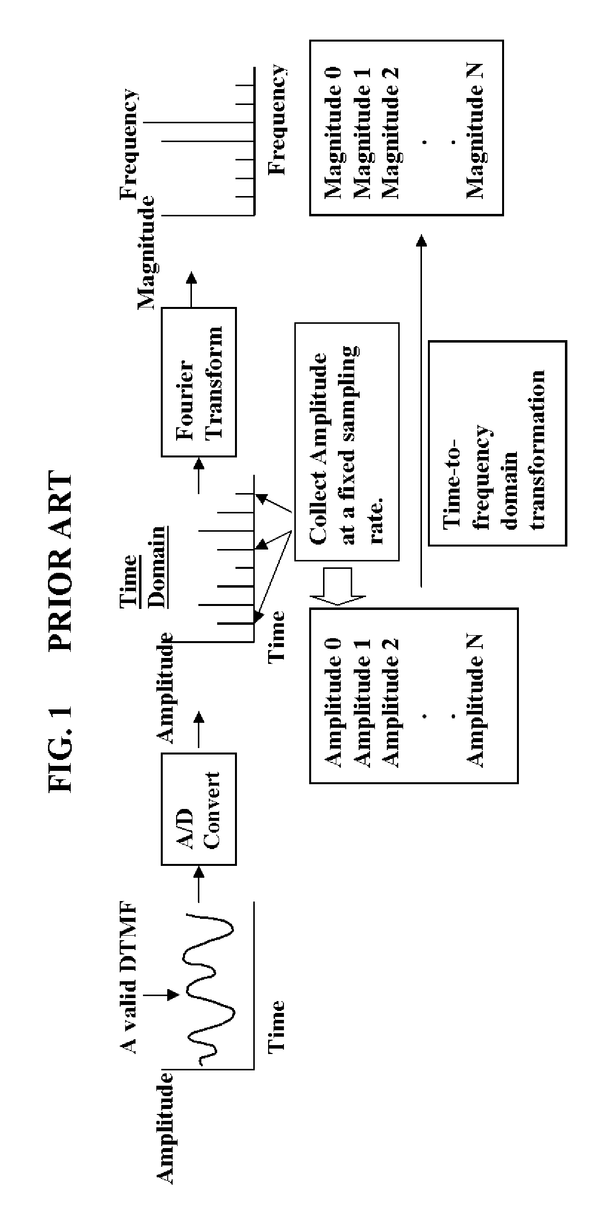
[0027] An understanding of the present invention requires an understanding of the Fourier Transform. See, for example, Ronald N. Bracewell, “The Fourier Transform,”Scientific American, June 1989, pp. 86-95. The human ear automatically and involuntarily performs a calculation that takes the intellect years of mathematical education to accomplish. The ear formulates a transform by converting sound—the waves of pressure traveling over time and through the atmosphere—into a spectrum, a description of the sound as a series of volumes at distinct pitches. The brain then turns this information into perceived sound.

[0028] A similar conversion can be done using mathematical methods on the same sound waves or virtually any other fluctuating signal that varies with respect to time. The Fourier transform is the mathematical tool used to make this conversion. Simply stated, the Fourier transform converts waveform data in the time domain into the frequency domain. The Fourier transform accomplis...


PUM


Abstract

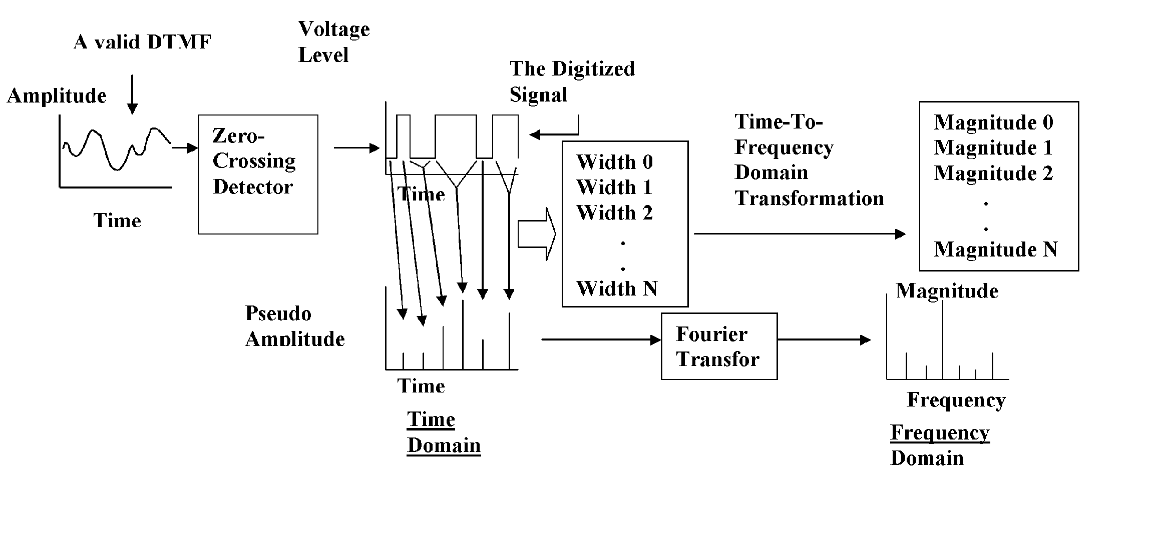
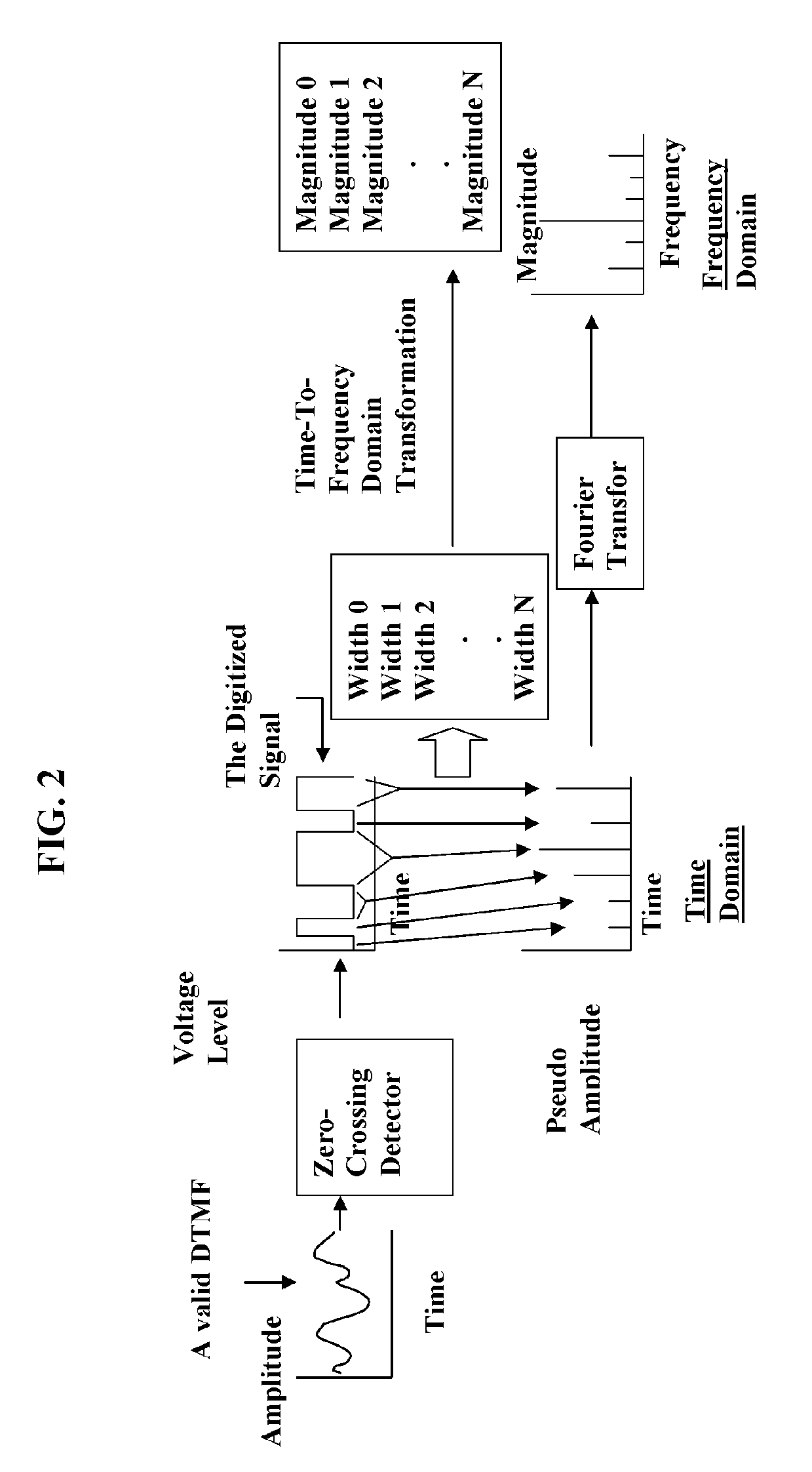
A method for decoding a DTMF tone which includes collecting the width of serial signals by measuring the time interval between zero-crossing points within a predetermined time; counting within the predetermined time the number of signal zero-crossing points; performing interpolation on the data produced by the collecting and counting steps with a Fourier transform; identifying a first frequency that has the strongest magnitude from the resulting data; and calculating the lower frequency of the tone being decoded by subtracting the first frequency from the average frequency of the digitized signal. The invention also includes apparatus that utilizes a zero-crossing detector for receiving a DTMF tone to be decoded and producing a digitized output; apparatus for collecting the width of serial signals by measuring the time interval between zero-crossing points within a predetermined time; apparatus for counting within the predetermined time the number of signal zero-crossing points; apparatus for performing interpolation on the data produced by the collecting and counting steps with a Fourier transform; apparatus for identifying a first frequency that has the strongest magnitude from the resulting data; and apparatus for calculating the lower frequency of the tone being decoded by subtracting the first frequency from the average frequency of the digitized signal.

Description

BACKGROUND OF THE INVENTION [0001] The invention relates to the use of audio tones to transmit data and particularly to decoding DTMF audio tones. Applications for this apparatus and method include telephony and other fields where data is transmitted by the use of audio tones. DTMF (Dual-tone Multi Frequency) is a tone composed of two sine waves of given frequencies. Individual frequencies are chosen so that it is quite easy to design frequency filters, and so that they can easily pass through telephone lines (where the maximum guaranteed bandwidth extends from about 300 Hz to 3.5 kHz). DTMF was not intended for data transfer; it is designed for control signals only. With standard decoders, it is possible to signal at a rate of about 10 “beeps” (=5 bytes) per second. DTMF standards specify 50 ms tone and 50 ms space duration. For shorter lengths, synchronization and timing are more difficult. [0002] DTMF is the basis for voice communications control. Modern telephony uses DTMF to di...

Claims


Application Information

Patent Timeline
IPC IPC(8): H04M3/00H04M5/00
CPCH04Q1/453
Inventor CHEN, HONG-JYH
Owner ADEMCO INC
Learn More