Wiring board and wiring apparatus

a technology of wiring apparatus and wire board, which is applied in the field of wiring board, can solve the problems of high cost of driver ics having the position detection function, deviating from the real position of the sensed position of an object on the display panel, and not being suitable for fine indication of position or handwritten character inpu

Inactive Publication Date: 2007-05-24
CANON KK
View PDF5 Cites 21 Cited by
  • Summary
  • Abstract
  • Description
  • Claims
  • Application Information

AI Technical Summary

Benefits of technology

[0013] An object of the present invention is to provide a display-integrated position detection apparatus without adding any new function to the driver IC nor changing wiring p...

Problems solved by technology

In such apparatuses, however, a sensed position of an object on the display panel often deviates from its true position because the display panel and the sensor panel are stacked with a distance.
They are not suitable for fine indication of position or handwritten character input.
When a pen input function, wherein scanning/signal lines are used as an antenna for position detection, is added to a di...

Method used


Image

  • Wiring board and wiring apparatus
  • Wiring board and wiring apparatus
  • Wiring board and wiring apparatus

Examples


first embodiment

1. First Embodiment

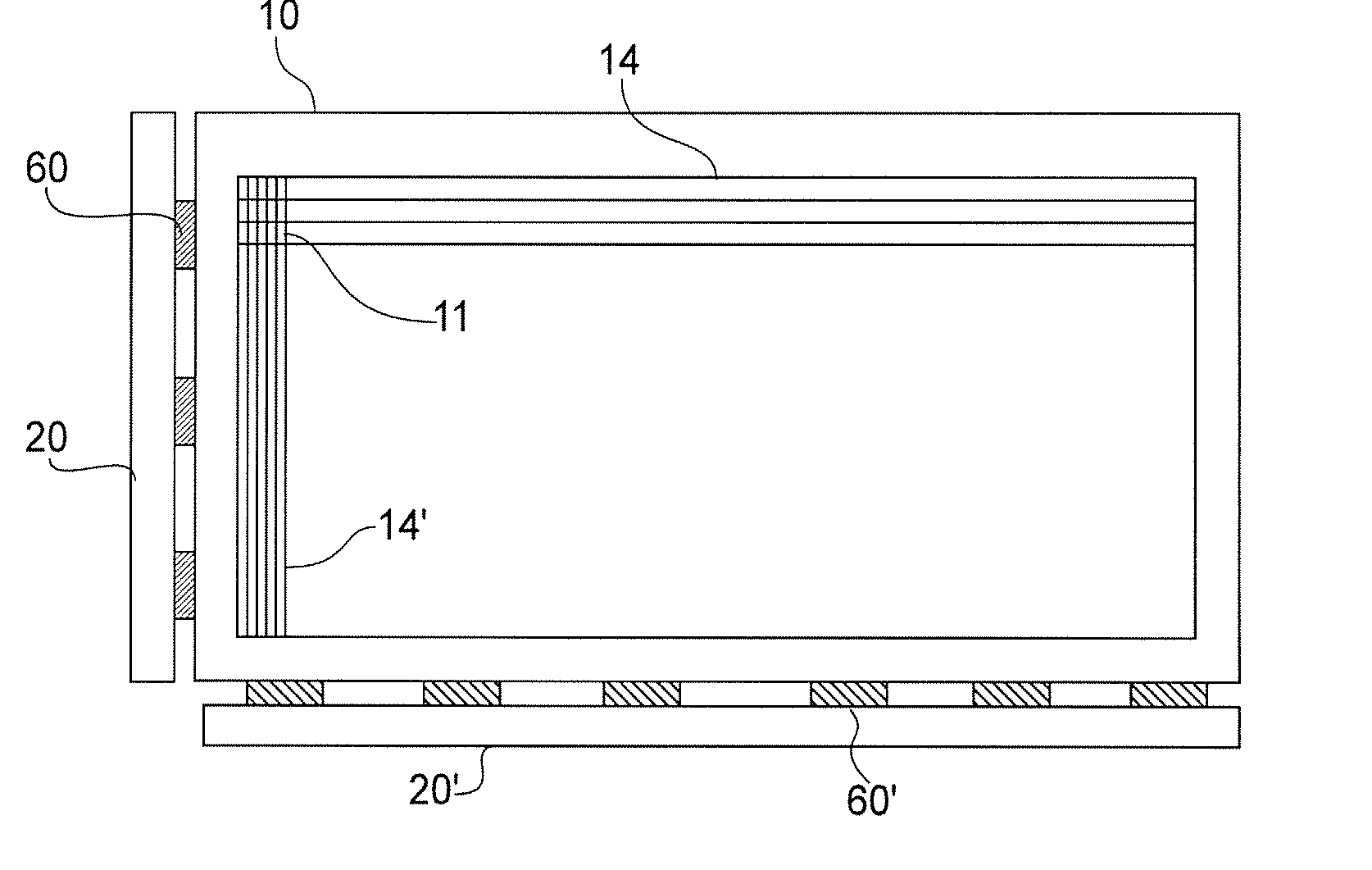
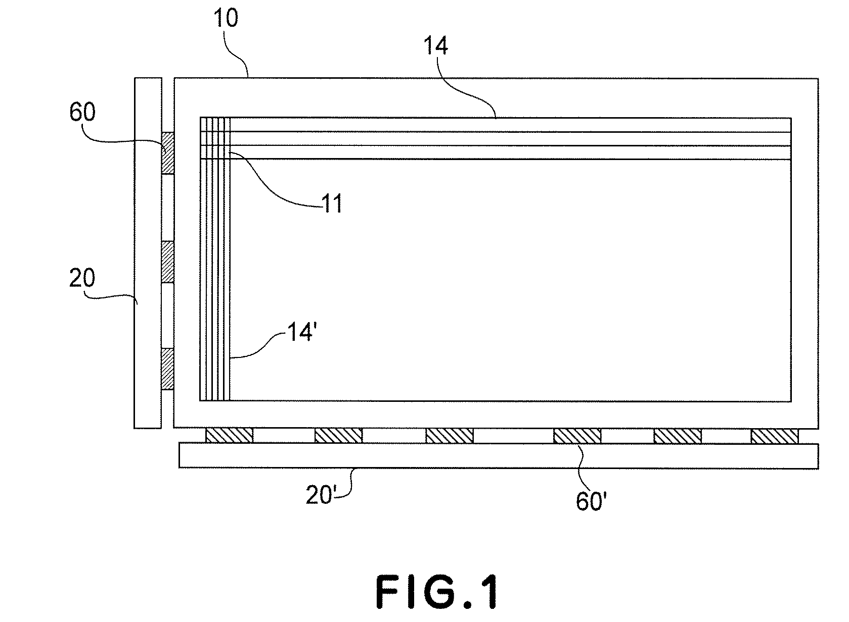
[0045]FIG. 1 is a constitutional view of a matrix display apparatus.

[0046] On a display panel 10, scanning signal lines (scanning lines) 14 disposed in parallel with each other on a substrate and signal lines 14′ disposed in parallel with each other on the substrate and perpendicular to the scanning signal lines 14 are formed in a manner of crossing with an overpass or underpass. At each of intersections of the scanning lines 14 and the signal lines 14′, a pixel 11 of a display device is disposed.

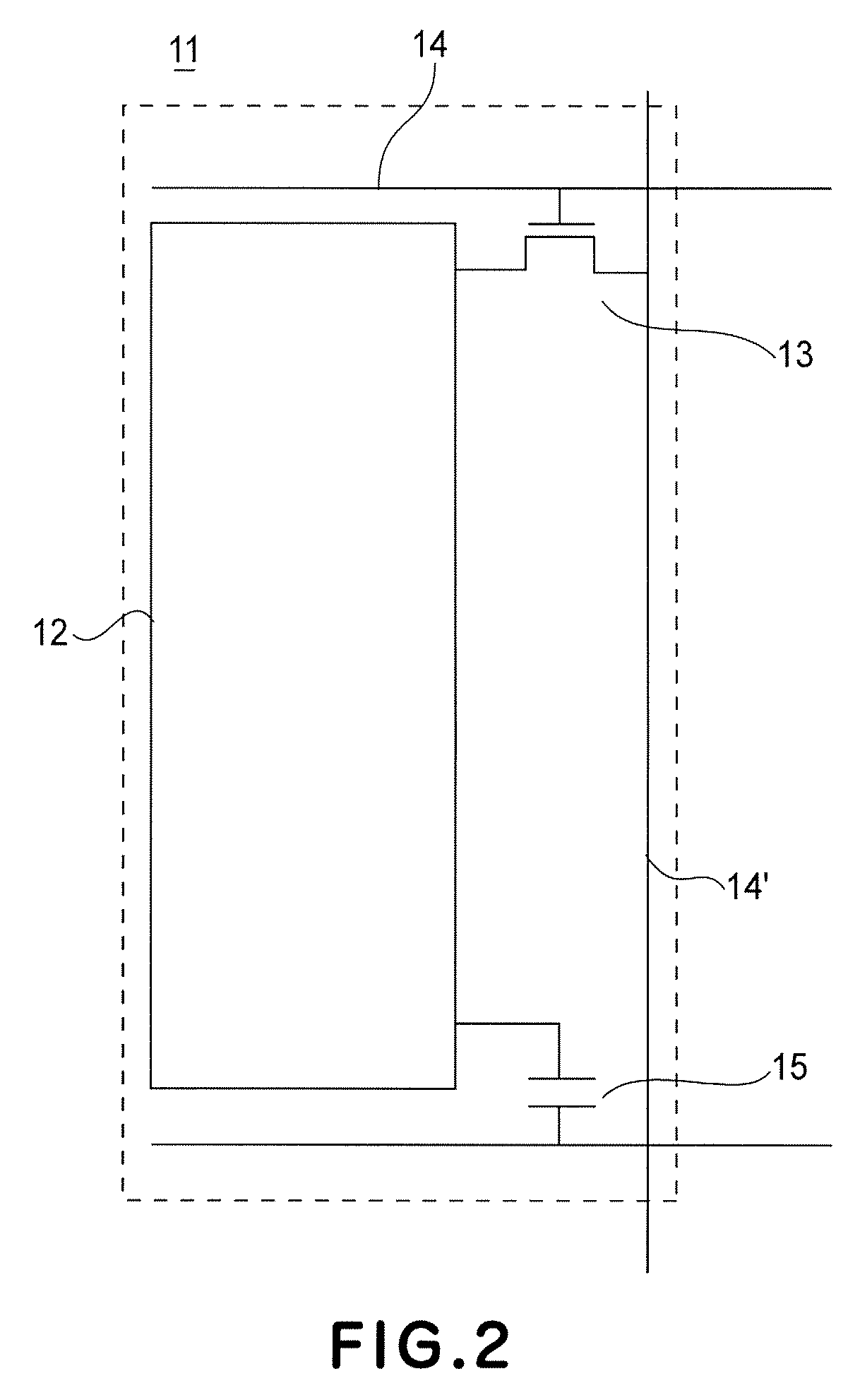
[0047] An enlarged view of the pixel 11 is shown in FIG. 2. In the pixel 11, a pixel electrode 12 and a thin film transistor (TFT) 13 are formed. A gate electrode of the TFT 13 is connected to the scanning line 14 and a source electrode of the TFT 13 is connected to the signal line 14′. Further, at a drain electrode, an auxiliary capacity 15 for holding a writing signal received at timing of a scanning signal is formed. The display panel 10 shown in FIG. 1 is an active ...

second embodiment

2. Second Embodiment

[0076] In this embodiment, the present invention is applied to a display panel in which a drive circuit is connected at both sides of scanning lines. In order to prevent signal delay, application of the same voltage signal from both sides of one signal line or one scanning line is frequently effected in a large-screen panel.

[0077]FIG. 6 is a schematic view showing a constitution of the display panel of this embodiment.

[0078] A display apparatus 100 includes a display panel 10 having a large number of pixels 12 disposed horizontally and vertically in a lattice-like shape. Around the display panel 10, a printed wiring board 20 on a scanning line drive circuit side, a printed wiring board (short-circuit board) 30 on an opposite scanning line drive circuit side, a printed wiring board 40 on a signal line drive circuit side, and a printed wiring board (short-circuit board) 50 on an opposite signal line drive circuit side are disposed. Further, to the printed wiring ...


PUM


Abstract

A wiring board includes conductive wirings, terminals and interconnecting lines connecting between them. First terminals establish a one-to-one correspondence with the interconnecting lines. The interconnecting lines terminate at the first terminals except at least one of the interconnecting lines. The interconnecting line which does not terminate at the first terminals terminates at the second terminal. The first terminal at which the interconnecting lines do not terminate is connected to the third terminal. The first terminals are connected to outputs of a driver IC mounted on a tape carrier package. The second and third terminal are connected to a switch via a through lead line of tape carrier package. When the second and third terminals are short-circuited by the switch, all the outputs of the driver IC is connected to the conductive wiring of the wiring board. When the second terminal is connected to the detection circuit by the switch, a signal on the wiring board is detected to determine a position of a pen.

Description

FIELD OF THE INVENTION AND RELATED ART [0001] The present invention relates to a wiring board including a substrate provided with a wiring pattern and a wiring apparatus including the wiring board and a circuit. More specifically, the present invention relates to a display panel provided with wiring for display and a display apparatus in which a circuit for sending a signal to the wiring is attached to the display panel. [0002] A display apparatus having a position indication function for effecting input operation by touching a button on a display screen with a hand-held pen or a finger has been put into practical use as game machines, personal computers, automated teller machines, ticket-vending machines, etc. In most of these apparatuses, an input function is provided by superposing a transparent touch sensor on a display panel. In such apparatuses, however, a sensed position of an object on the display panel often deviates from its true position because the display panel and the ...

Claims


Application Information

Patent Timeline
IPC IPC(8): H05K1/00G06F3/041
CPCG02F1/13338G02F1/13452G06F3/0412G06F3/046H05K1/117H05K1/147H05K3/361H05K2201/09781
Inventor SHIKINA, NORIYUKI
Owner CANON KK
Why Eureka
Try Eureka