Navigational mirror system for a vehicle

a mirror system and vehicle technology, applied in wave based measurement systems, navigation instruments, data processing applications, etc., can solve the problems of increasing the cost of the service, difficulty in remembering full directions, etc., and achieve the effect of reducing the cost of the instruction servi

Inactive Publication Date: 2007-05-24
DONNELLY CORP
View PDF99 Cites 73 Cited by
  • Summary
  • Abstract
  • Description
  • Claims
  • Application Information

AI Technical Summary

Benefits of technology

[0019] The present invention thus provides for step-by-step instructions or driving directions to the driver of a vehicle as the driver is driving the vehicle according to the instructions. Each step or instruction is provided either after the previous step or instruction has been completed or as the vehicle approaches a turn or intersection or location where the next step is to be performed, so that the driver is not overwhelmed with multiple instructions to remember as the driver drives the vehicle toward the targeted destination. The control or the remote source or service center is operable to electronically or digitally or otherwise tag, key, code or otherwise associate each instruction or step with a geographic location or waypoint, and the control is operable to only display that instruction when the geographic location tagged to the instruction generally matches the actual, current geographic position of the vehicle. All of the instructions are provided or downloaded to the vehicle during a single, short communication with the remote source or service center via the telematics system, so as to avoid multiple communications to the remote service center or a lengthy communication with the remote service center, thereby reducing the cost of the instruction service to the driver of the vehicle.

Problems solved by technology

The driver is then typically expected to remember several directional driving instructions and often has difficulty in remembering the full directions.
Although the driver may optionally remain on the line with the service center operator until the driver reaches the intended destination, which may take many minutes, such as ten, fifteen, twenty minutes or more, and / or the driver may call back to the service center for updated directions, these actions increase the cost of the service, since the service center typically charges for such calls.

Method used


Image

  • Navigational mirror system for a vehicle
  • Navigational mirror system for a vehicle
  • Navigational mirror system for a vehicle

Examples


Embodiment Construction

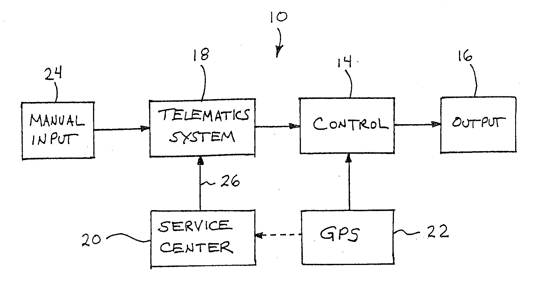
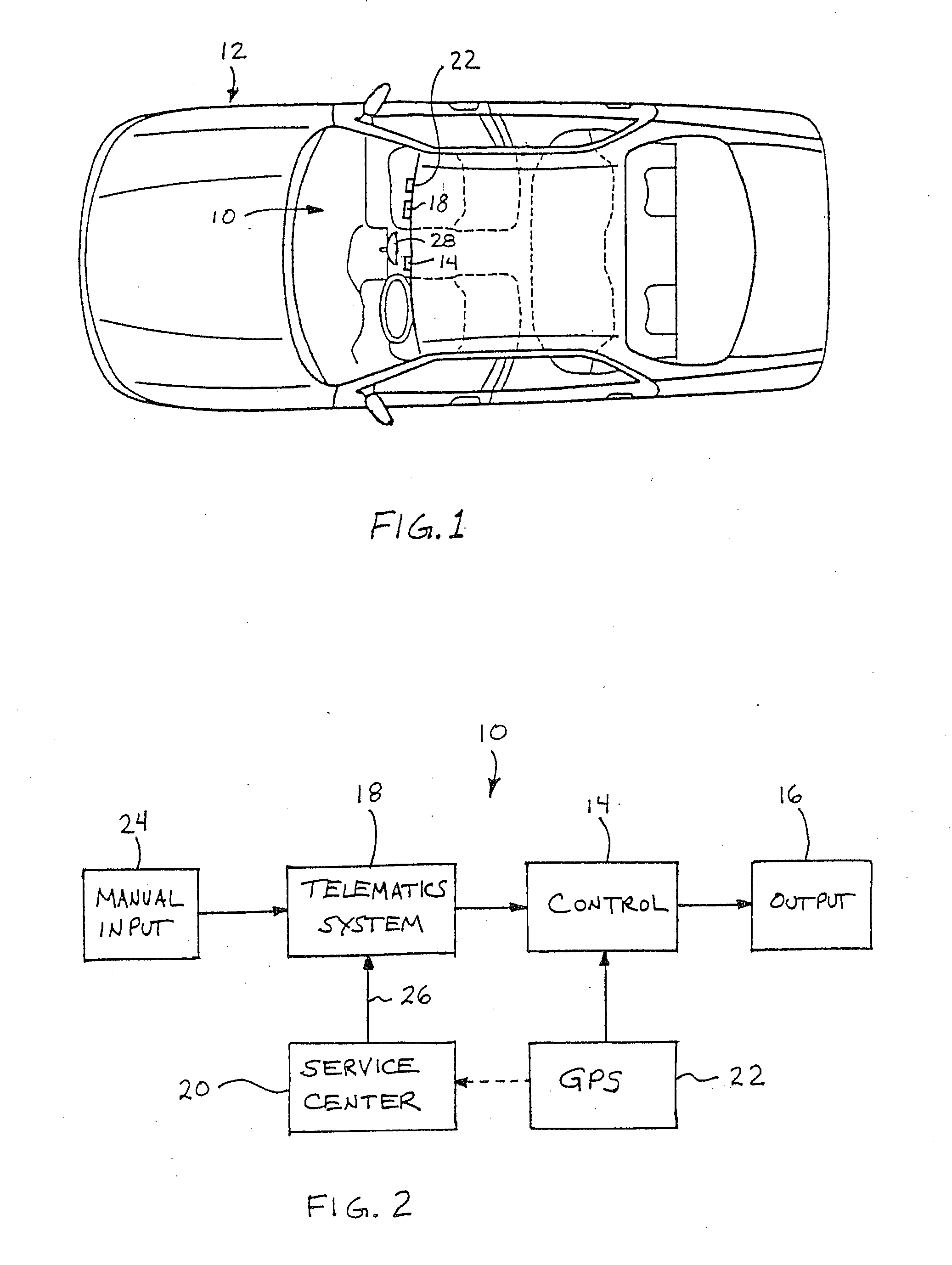
[0025] Referring now to the drawings and the illustrative embodiments depicted therein, a navigation system 10 of a vehicle 12 includes a control 14 which is operable to communicate an output 16, such as step-by-step directions or driving instructions, to a driver of the vehicle based on an initial, current or present geographic position of the vehicle and the desired or targeted final destination of the vehicle (FIGS. 1 and 2). The initial geographic position of the vehicle and the targeted destination is communicated to a remote source or service center 20 via a telematics system 18 of the vehicle and a global positioning system 22 of the vehicle. In response to a user input 24 from the driver or other occupant of the vehicle and the initial geographic position of the vehicle, the service center 20 provides or downloads a set of instructions or driving directions 26, which is received by the control 14 from the service center via the telematics system or wireless communication sys...


PUM


Abstract

A navigational mirror system for a vehicle includes an interior rearview mirror having a reflective element. A display, optionally a video display, is disposed to the rear of the reflective element and emits light when actuated that passes through the reflective element to be visible to a driver of the vehicle viewing a front portion of the reflective mirror element. A user input comprising a destination address is provided from a driver of the vehicle when the vehicle is at an initial geographic location. The display displays driving instructions that provide instructions to the destination address. The driving instructions are viewable by a person viewing the front portion of the reflective element. A particular instruction of the driving instructions is preferably displayed when it is appropriate to display the particular instruction to the driver of the vehicle.

Description

CROSS REFERENCE TO RELATED APPLICATIONS [0001] The present application is a continuation of U.S. patent application Ser. No. 10 / 645,762, filed Aug. 20, 2003 (Attorney Docket DON01 P-1103), which claims priority of U.S. provisional applications, Ser. No. 60 / 406,166, filed Aug. 27, 2002 by Taylor et al. for VEHICLE NAVIGATION SYSTEM FOR USE WITH A TELEMATICS SYSTEM (Attorney Docket DON01 P-1022); Ser. No. 60 / 405,392, filed Aug. 23, 2002 by Kevin C. McCarthy for VEHICLE NAVIGATION SYSTEM FOR USE WITH A TELEMATICS SYSTEM (Attorney Docket DON01 P-1019); and Ser. No. 60 / 404,906, filed Aug. 21, 2002 by Taylor for BIOMETRIC VEHICLE SEATING ADJUSTMENT SYSTEM (Attorney Docket DON01 P-1018), and which is a continuation-in-part of U.S. patent application Ser. No. 10 / 456,599, filed Jun. 6, 2003 by Weller et al. for INTERIOR REARVIEW MIRROR SYSTEM WITH COMPASS, now U.S. Pat. No. 7,004,593 (Attorney Docket DON01 P-1076), and which is a continuation-in-part of U.S. patent application Ser. No. 10 / 28...

Claims


Application Information

Patent Timeline
Patent Type & Authority Applications(United States)
IPC IPC(8): G01C21/00B60N2/90G01S19/48B60R1/12G01C21/36G01S5/14G06Q20/00
CPCB60C23/0408G01C21/26B60Q1/2665B60Q9/00B60R1/00B60R1/088B60R1/12B60R2001/1215B60R2001/1253B60R2300/8066G01C21/36G01C21/365H04N7/183B60R11/04G06K9/00805G01C21/00G01C21/20B60N2/448B60N2/976G06V20/58H04N23/90B60Q5/006B60R2300/105B60R2300/301B60R2300/406G01S13/862G01S13/865G01S13/867H04N7/181B60R2300/207B60R2300/806B60R2300/8093G06T5/006G06T2207/30252H04N5/265
Inventor TAYLOR, DAVID W.MCCARTHY, KEVIN C.LYNAM, NIALL R.SCHOFIELD, KENNETH
Owner DONNELLY CORP
Why Eureka
Try Eureka