Surgical sagittal saw with indexing head and toolless blade coupling assembly for actuating an oscillating tip saw blade and oscillating tip saw blade with self cleaning head

a technology of indexing head and saw blade, which is applied in the field of surgical sagittal saw and complementary saw blade assembly, can solve the problems of no longer precisely defining the intended cut line, the slot may become so wide, and the limit of the assembly is associated with it, so as to minimize the effort required to insert and remove the blade assembly. , the effect of easy releas

Active Publication Date: 2007-05-31
STRYKER EURO OPERATIONS HLDG LLC
View PDF17 Cites 68 Cited by
  • Summary
  • Abstract
  • Description
  • Claims
  • Application Information

AI Technical Summary

Benefits of technology

[0019] This invention relates to a new and useful surgical sagittal saw and a complementary blade assembly designed for use with the saw. The sagittal saw of this invention has a head with a toolless coupling assembly for releasably holding the blade assembly in place. The coupling assembly also does not include components that are removed from the head. The saw head is also relatively easy to release from a locked indexed position, rotate to a new index position and then lock in the new index position. The blade assembly of this invention ejects debris that enter the blade bar.
[0020] More specifically, the saw of this invention is provided with an assembly that allows the oscillating unit to which the blade drive rods are attached to move. This minimizes the efforts required to insert and remove the blade assemblies. The coupling assembly clamps the blade bar in place. Neither of these assemblies have components that are removed from the saw head in order to remove and replace the attached blade assembly.
[0021] Also integral with the saw head is a first biasing member that holds the head against the saw housing component from which the head extends. A lock assembly prevents the rotation of the saw head. A second biasing member, part of the lock assembly, latching the locking assembly in position. Collectively, these sub-assemblies make it relatively easy to unlock, index and relock the saw head in a fixed angular orientation.
[0022] The blades assembly of this invention includes both the blade bar and a blade head that is pivotally attached to the bar. Openings are formed in both the blade bar and blade head. Collectively, these openings are positioned to form a discharge path through which debris that enter the bar are ejected. This essentially eliminates the possibility that entrance of such material into the blade bar can adversely affect blade operation.

Problems solved by technology

However, some limitations are associated with these assemblies.
Eventually the slot may become so wide that it no longer precisely defines the intended cut line.
If an accurate cut is desired this movement is, at a minimum, undesirable.
Moreover, the wearing of the material forming the cutting guide generates a fine dust of material.
Some of this dust inevitably settles on the surgical site at which the procedure is being performed.
Consequently, during the procedure, the surgical personnel are required to spend an appreciable amount of time flushing the site to remove this dust.
One further disadvantage of this blade galling it consumes power.
The power expended overcoming the blade galling-induced friction reduces the overall amount of power available to actuate the saw.
Moreover, as a consequence of the saw blade galling against a surface of the cutting guide, then pulling away from this surface, there is some jerking of the blade.
Over time, having to so hold the saw to overcome this vibration can be significantly mentally and physically fatiguing.
However, this assembly relies on removable threaded fasteners to removably hold the blade assembly to the saw head.
Having to perform these steps in surgery can lengthen the overall time it takes to perform the procedure.
Also, debris from cut tissue can enter the bars of some blade assemblies.
These debris can potentially inhibit blade head oscillation.
Often, surgical personnel find it difficult to manually overcome the force imposed by this spring in order to rotate the saw head.

Method used


Image

  • Surgical sagittal saw with indexing head and toolless blade coupling assembly for actuating an oscillating tip saw blade and oscillating tip saw blade with self cleaning head
  • Surgical sagittal saw with indexing head and toolless blade coupling assembly for actuating an oscillating tip saw blade and oscillating tip saw blade with self cleaning head
  • Surgical sagittal saw with indexing head and toolless blade coupling assembly for actuating an oscillating tip saw blade and oscillating tip saw blade with self cleaning head

Examples


Embodiment Construction

I. Overview

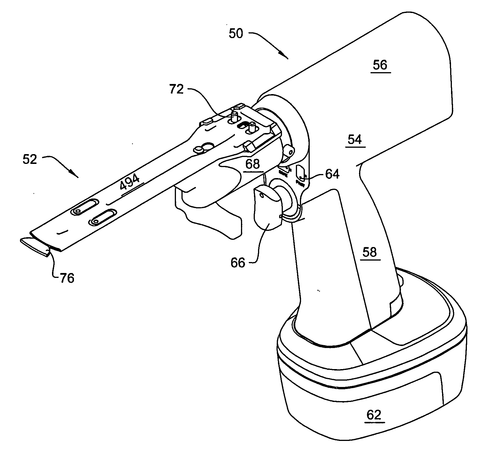
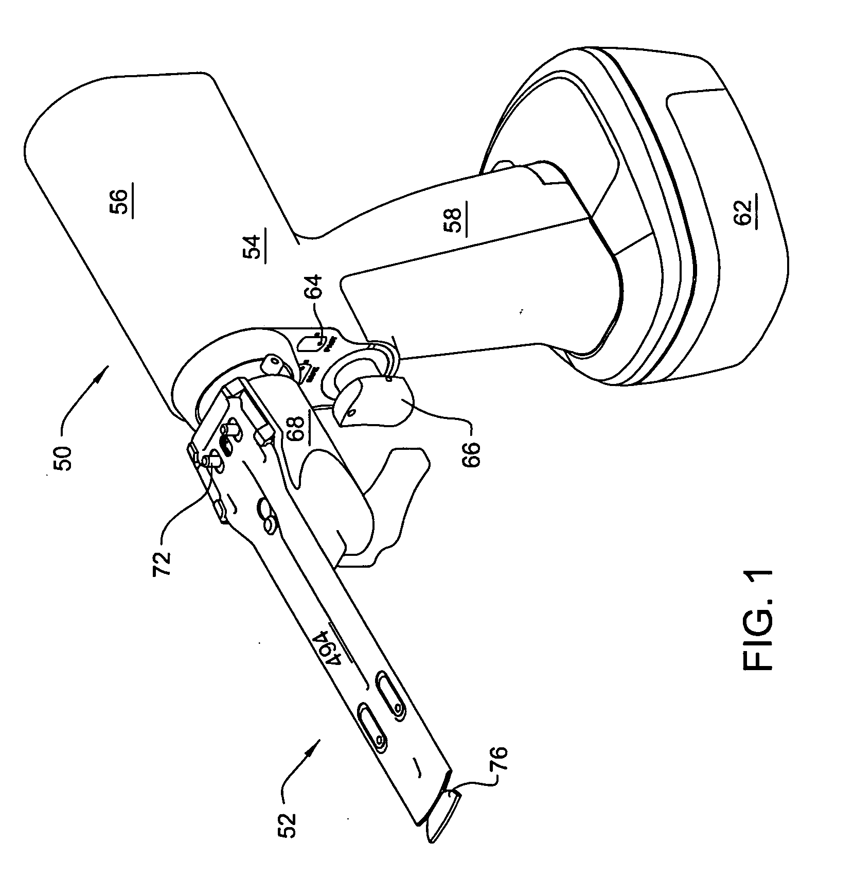
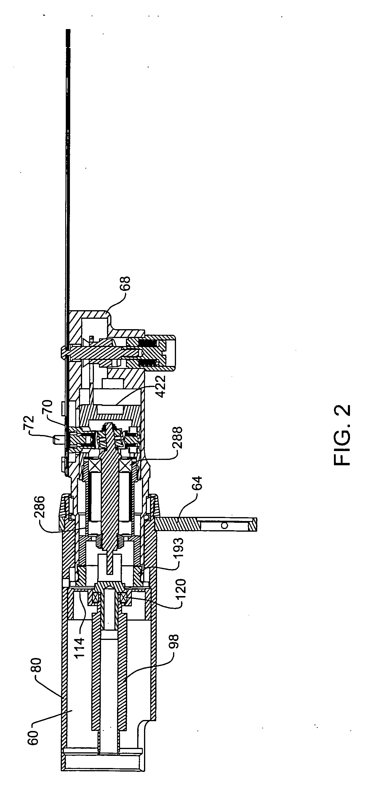
[0106]FIGS. 1 and 2 depict the surgical saw 50 of this invention and the blade assembly 52 used with the saw. Saw 50 includes a housing 54. The housing 54 has an elongated, top-located barrel section 56. A pistol-grip shaped handle 58, also part of housing 54, extends downwardly from barrel section 56. A motor 60 is disposed inside the housing barrel section 56. In some versions of the invention, motor 60 is a brushless, sensorless DC motor. This is exemplary, not limiting. In other versions of the invention, the motor 60 may be a DC motor with brushes and / or sensors, an AC driven motor or a motor that is pneumatically or hydraulically driven. In the illustrated version of the invention, saw 50 is a cordless power tool. A battery 62 removably attached to the butt end of handle 58 contains a charge for energizing the motor. Again, it should be understood that the invention is not so limited. In alternative versions of the invention, a power cord, an air line or a fluid lin...


PUM

PropertyMeasurementUnit
thicknessaaaaaaaaaa
thicknessaaaaaaaaaa
thicknessaaaaaaaaaa

Abstract

A surgical sagittal saw with an indexing head. The saw actuates a blade assembly that includes a bar from which a blade head extends. An oscillating head extends upwardly from the saw head. The oscillating head, in addition is mounted to the saw head to be able to rotate around its longitudinal axis and so that it can move along the saw head. A biasing spring normally holds the oscillating head in a fixed position. When the oscillating head is in the fixed position, the oscillating head holds the blade assembly against a restraining bracket integral with the saw head. Manual force is used to overcome the biasing spring to allow replacement and removal of the blade assembly.

Description

PRIORITY CLAIM [0001] This application claims priority under 35 U.S.C. Sec. 119 from U.S. Pat. App. No. 60 / 715,821 filed 10 Sep. 2005.FIELD OF THE INVENTION [0002] This invention is related generally to a surgical saw and, more particularly, a surgical sagittal saw and a complementary saw blade assembly. BACKGROUND OF THE INVENTION [0003] A sagittal saw is a powered surgical tool that is typically used in an orthopedic surgical procedure. A sagittal saw generally includes a handpiece that houses a motor and the complementary control circuit that regulates actuation of the motor. Extending forward, distally, from the handpiece is a head. Internal to the head is an oscillating shaft. Removably attached to the oscillating shaft is a saw blade. The exposed distal front edge of the blade is formed with teeth. The teeth cut the tissue against which the blade is applied. A drive mechanism internal to the housing generates power. This power is applied to actuate the oscillating shaft that t...

Claims


Application Information

Patent Timeline
Patent Type & Authority Applications(United States)
IPC IPC(8): B26B11/00
CPCA61B17/14A61B17/141A61B19/5244A61B17/148A61B2019/5251A61B2019/5268A61B2017/00734A61B2034/2068A61B34/20A61B2034/2051Y10T29/49826Y10T29/49947A61B17/142A61B2017/00526
Inventor WALEN, JAMES G.BRINDLEY, ROBERTCOSGROVE, LIAMLAND, TREVOR M.
Owner STRYKER EURO OPERATIONS HLDG LLC
Why Eureka
Try Eureka