Drillable bridge plug

a bridge plug and plug-in technology, which is applied in the direction of fluid removal, borehole/well accessories, construction, etc., can solve the problems of excessive casing wear, long drill-out times, and high undesirable effects

Inactive Publication Date: 2007-05-31
BJ SERVICES CO
View PDF94 Cites 134 Cited by
  • Summary
  • Abstract
  • Description
  • Claims
  • Application Information

AI Technical Summary

Benefits of technology

[0022] In one embodiment the apparatus includes a hole in the mandrel extending at least partially therethrough. In another embodiment the hole extends all the way through the mandrel. In the embodiment with the hole extending all the way therethrough, the mandrel may include a valve arranged in the hole facilitating the flow of cement or other fluids, gases, or slurries through the mandrel, thereby enabling the invention to become a cement retainer.

Problems solved by technology

One typical problem with conventional drillable bridge plugs is that without some sort of locking mechanism, the bridge plug components tend to rotate with the drill bit, which may result in extremely long drill-out times, excessive casing wear, or both.
Long drill-out times are highly undesirable as rig time is typically charged for by the hour.
Another typical problem with conventional drillable plugs is that the conventional metallic construction materials, even though brittle, are not easy to drill through.
The plugs are generally required to be quite robust to achieve an isolating seal, but the materials of construction may then be difficult to drill out in a reasonable time.
It would be desirable to create a plug that did not require significant forces to be applied to the drill-bit such that the drilling operation could be accomplished with a coiled tubing motor and bit; however, conventional metallic plugs do not enable this.
In addition, when several plugs are used in succession to isolate a plurality of zones within the wellbore, there may be significant pressures on the plug from either side.
Prior art downhole tools do not allow the same tool to be converted from a bridge plug to a frac plug.
Not only does this require twp tools, but the time required to remove the bridge plug and set the frac plug or cement retainer may be costly to the operation.
It has been discovered that when it is desired to remove the prior art frac plugs or cement retainers, the flapper may tend to rotate within the mandrel with the mill or drill bit, thus increasing the removal time.
Once the hinge is milled or drilled out in these prior art flappers, the flapper is free to rotate with the drill bit or mill within the mandrel, thus making the remainder of the removal of the flapper time-intensive.

Method used


Image

  • Drillable bridge plug
  • Drillable bridge plug
  • Drillable bridge plug

Examples


Embodiment Construction

[0098] Illustrative embodiments of the invention are described below. In the interest of clarity, not all features of an actual implementation are described in this specification. It will of course be appreciated that in the development of any such actual embodiment, numerous implementation-specific decisions must be made to achieve the developers' specific goals, such as compliance with system-related and business-related constraints, that will vary from one implementation to another. Moreover, it will be appreciated that such a development effort might be complex and time-consuming, but would nevertheless be a routine undertaking for those of ordinary skill in the art having the benefit of this disclosure.

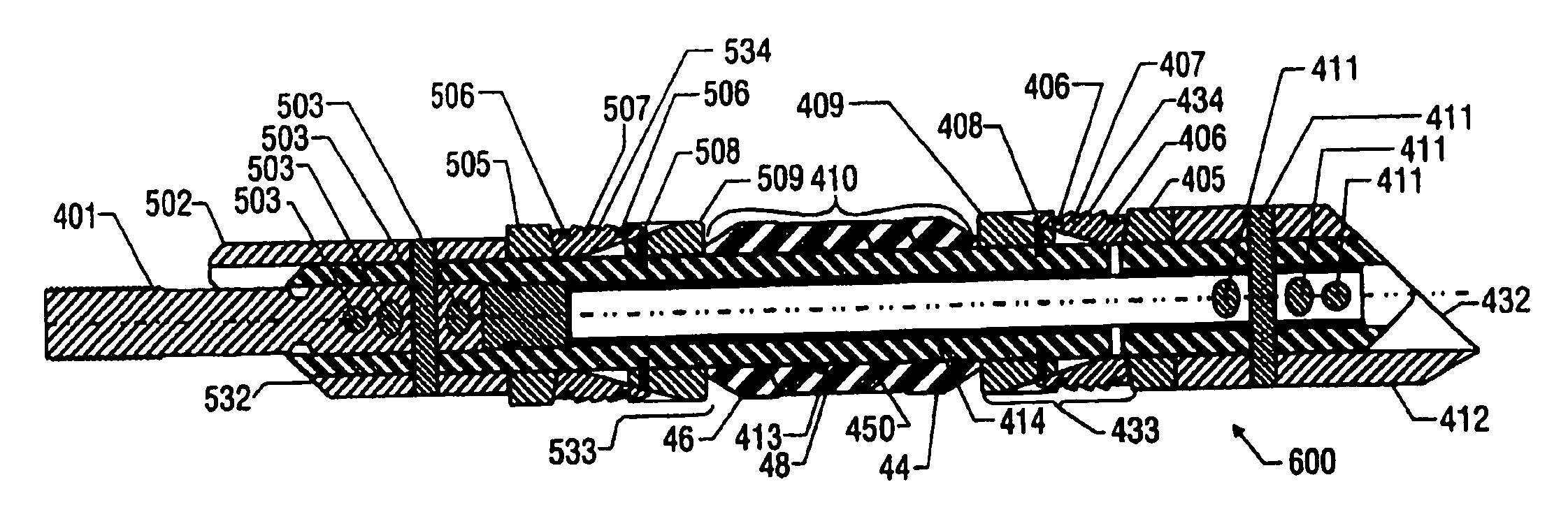
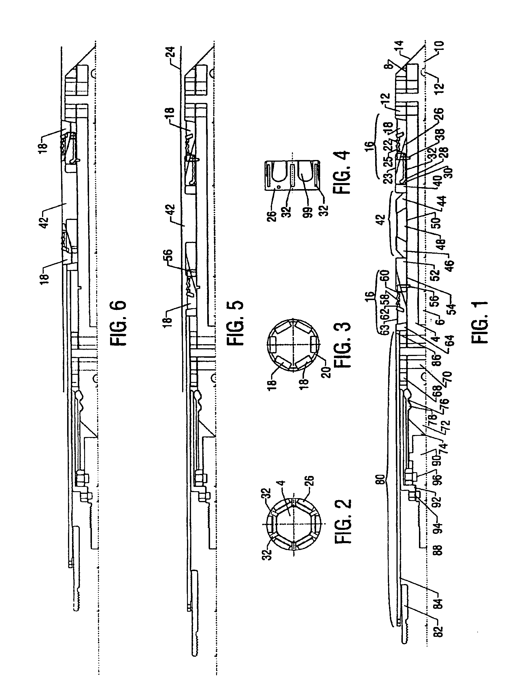
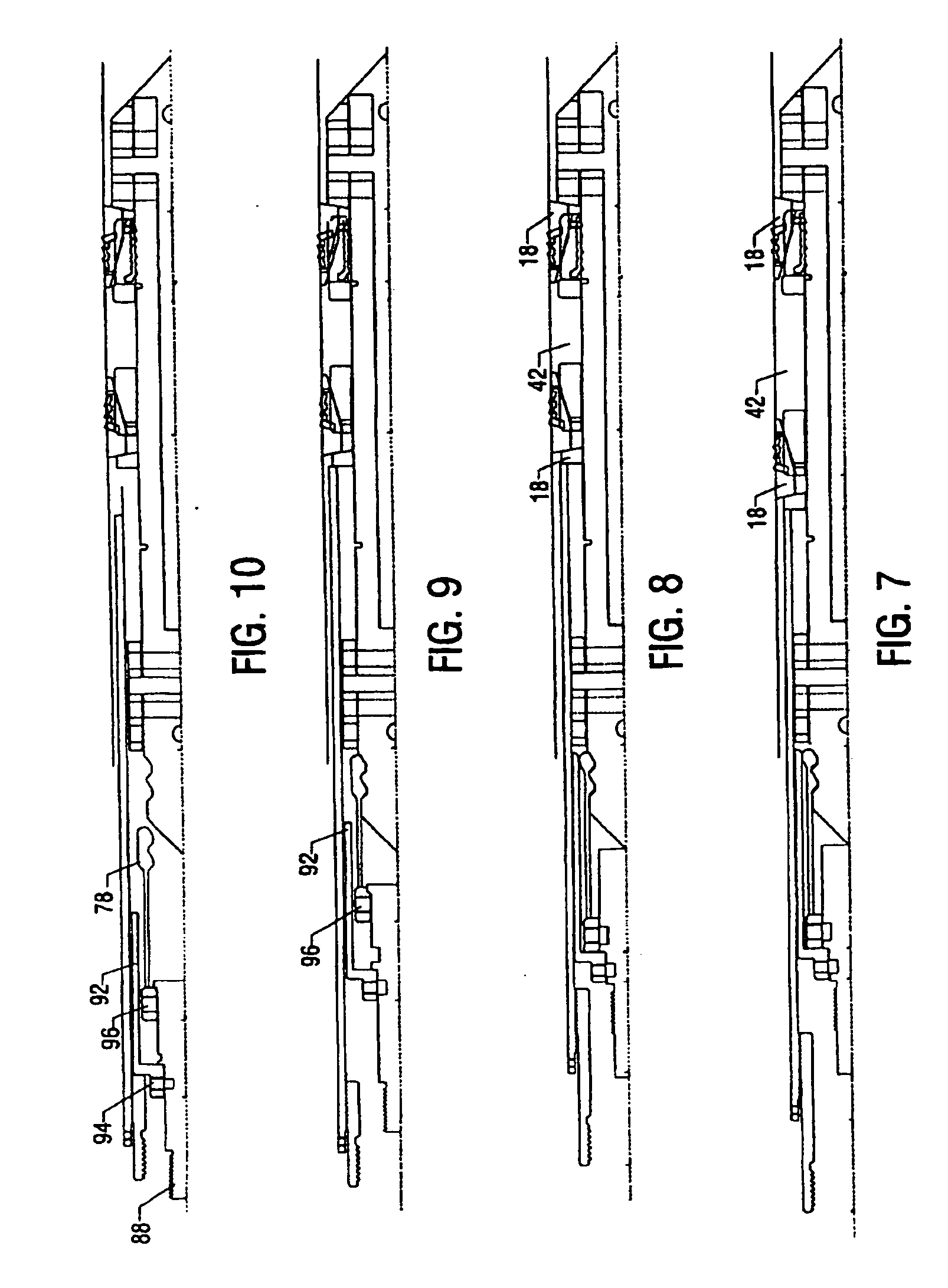
[0099] Turning now to the drawings, and in particular to FIGS. 1 and 13, a subterranean plug assembly 2 in accordance with one embodiment of the disclosed method and apparatus is shown. Plug assembly 2 is shown in the running position in FIGS. 1 and 13. Plug assembly 2 is shown ...


PUM


Abstract

A method and apparatus for use in a subterranean well is described. The apparatus typically includes a mandrel and a packing element. The mandrel may have an outer surface and a non-circular cross-section and the packing element may be arranged about the mandrel, the packing element having a non-circular inner surface matching the mandrel outer surface such that concentric rotation between the mandrel and the packing element is precluded. The apparatus may include slips having cavities to facilitate removal of the apparatus. The apparatus also may include a valve for controlling upward fluid flow through a hollow mandrel. The valve may include a flapper having at least one tab to engage at least one recession in the mandrel such that rotation between the mandrel and the valve is precluded when the valve is in a closed position. The apparatus may further include a central member which is releaseably attached to the mandrel by a release mechanism.

Description

CROSS-REFERENCE TO RELATED APPLICATIONS [0001] This application is a continuation-in-part of application Ser. No. 10 / 658,979, filed Sep. 10, 2003, entitled “Drillable Bridge Plug,” which is a continuation-in-part of application Ser. No. 10 / 146,467, filed May 15, 2002 and issued as U.S. Pat. No. 6,708,770 on Mar. 23, 2004, entitled “Drillable Bridge Plug”, which is a continuation-in-part application of Ser. No. 09 / 844,512, filed Apr. 27, 2001 and issued as U.S. Pat. No. 6,578,633 on Jun. 17, 2003, entitled “Drillable Bridge Plug,” which is a continuation-in-part of application Ser. No. 09 / 608,052, filed Jun. 30, 2000 and issued as U.S. Pat. No. 6,491,108 on Dec. 10, 2003, entitled “Drillable Bridge Plug,” each of which are incorporated herein in its entirety by reference.BACKGROUND OF THE INVENTION [0002] 1. Field of the Invention [0003] This invention relates generally to methods and apparatus for drilling and completing subterranean wells and, more particularly, to methods and appa...

Claims


Application Information

Patent Timeline
Patent Type & Authority Applications(United States)
IPC IPC(8): E21B33/12
CPCE21B33/134E21B2034/005E21B2200/05
Inventor SLUP, GABRIELLEHR, DOUGLAS J.ALLEN, TOMMY J.COX, BLAKE ROBINDEEL, DONALD W.ZIMMERMAN, SAMUEL MARK
Owner BJ SERVICES CO
Why Eureka
Try Eureka