Magnetorheological damper system

a damper system and magnetorheological technology, applied in the direction of shock absorbers, machine supports, mechanical equipment, etc., can solve the problems of affecting the handling and ride of the vehicle, reducing the efficiency of the damper system, so as to achieve the effect of straightforward manufacturing and assembly

Inactive Publication Date: 2007-05-31
MILLENWORKS
View PDF11 Cites 66 Cited by
  • Summary
  • Abstract
  • Description
  • Claims
  • Application Information

AI Technical Summary

Benefits of technology

[0013] It is a further object of the present invention to provide a damping device that operates correctly and efficiently at very high and very low damping forces.
[0021] In another exemplary embodiment of the present invention, there is contemplated a method of damping forces that includes providing a magnetorheological (MR) damping system on a structure that encounters periodic external forces. The damping system has a movable electromagnet and a stationary electromagnet, both of which being in fluid communication with magnetorheological fluid. The system senses at least one external motion variable on said structure that causes movement of said movable electromagnet. The system then energizes at least said movable electromagnet in response to said sensed external force. The system will energize both said movable electromagnet and said stationary electromagnet when said sensed external motion variable exceeds a predetermined threshold amount such that cavitation of said damping system is substantially prevented in said damping system beyond said predetermined threshold.

Problems solved by technology

One of the persistent design constraints in the field of engineering is vibration and / or force impact and / or fatigue management.
Such design constraints, however, are no more self evident than in the field of vehicle design.
Indeed, when it comes to vehicle design, it may be said that this adverse active environment is perhaps the primary design constraint.
If there was a spring alone (i.e., no cylindrical tubes discussed above) between the tire / wheel and the frame, there is a risk that this difficult terrain will cause the spring to resonate, a condition that adversely effects the handling and ride of the vehicle.
That is, the added resistance to movement of the tubes due to the restrictive flow of fluid resulting from movement of the piston thereby dampens the forces that would otherwise cause the spring to extend or compress.
There are, however, practical limits as to how much shock performance may be changed by making such alterations.
However, the inventors are not aware of any prior art MR devices capable of correctly operating at very high damping forces and / or that support wide ranges of damping forces without the system either encountering undesired cavitation or without being severely damaged.
Nor are the inventors aware of any prior art MR devices that have adequate bandwidth for effective isolation of the high frequency road inputs often encountered with difficult terrains.

Method used


Image

  • Magnetorheological damper system
  • Magnetorheological damper system
  • Magnetorheological damper system

Examples


Embodiment Construction

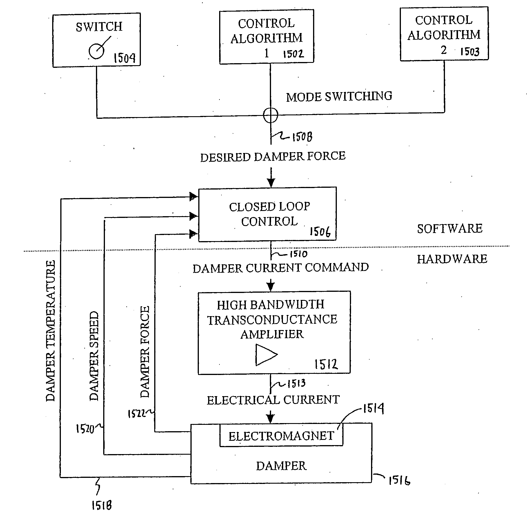
[0042] Discussed below is a detailed description of various illustrated embodiments of the present invention. This description is not meant to be limiting but rather to illustrate the general principles of the present invention. It will be appreciated by the reader that the principles constituting the invention can be applied with great success to any number of applications that require management of shock forces, vibration, etc.

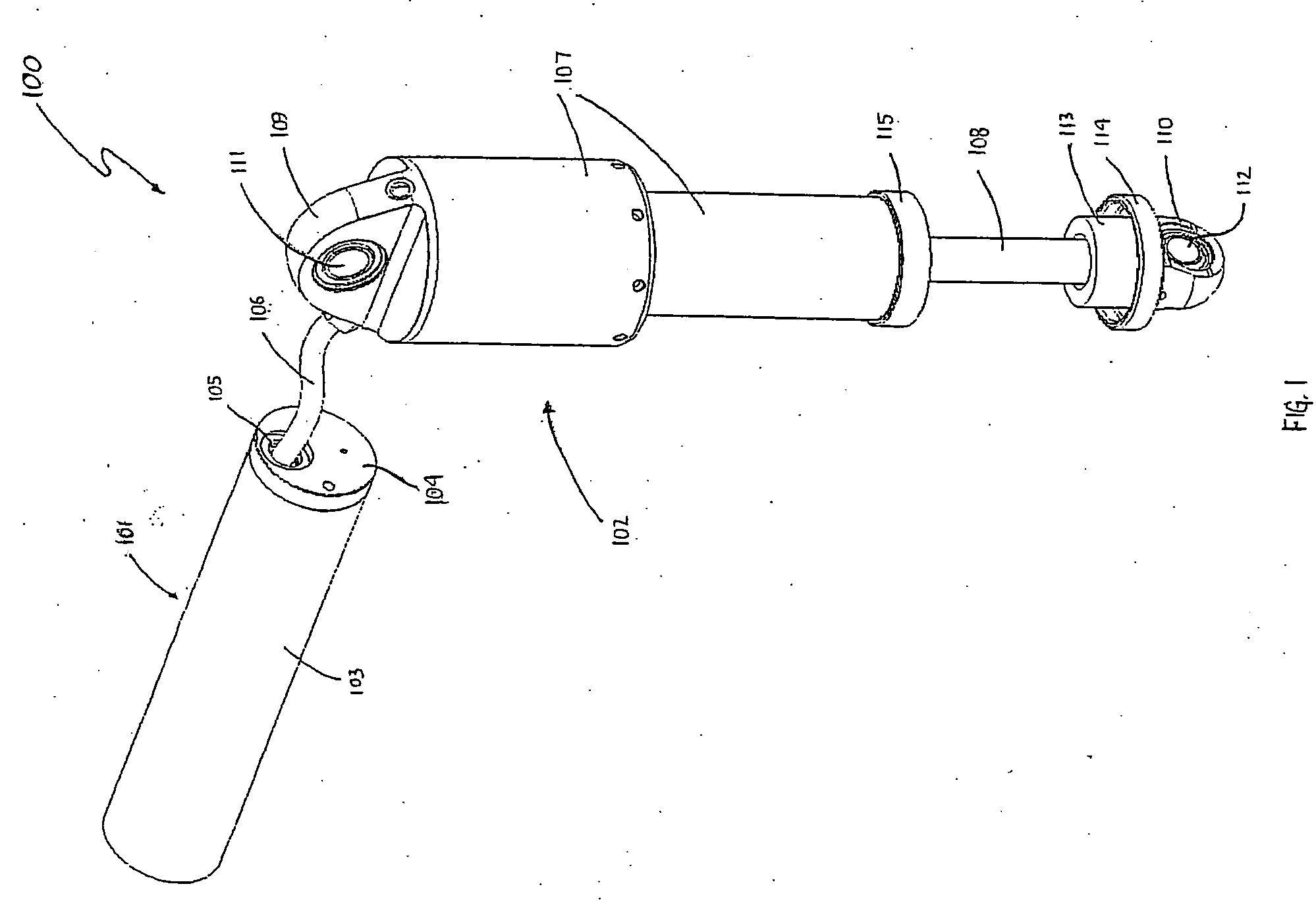
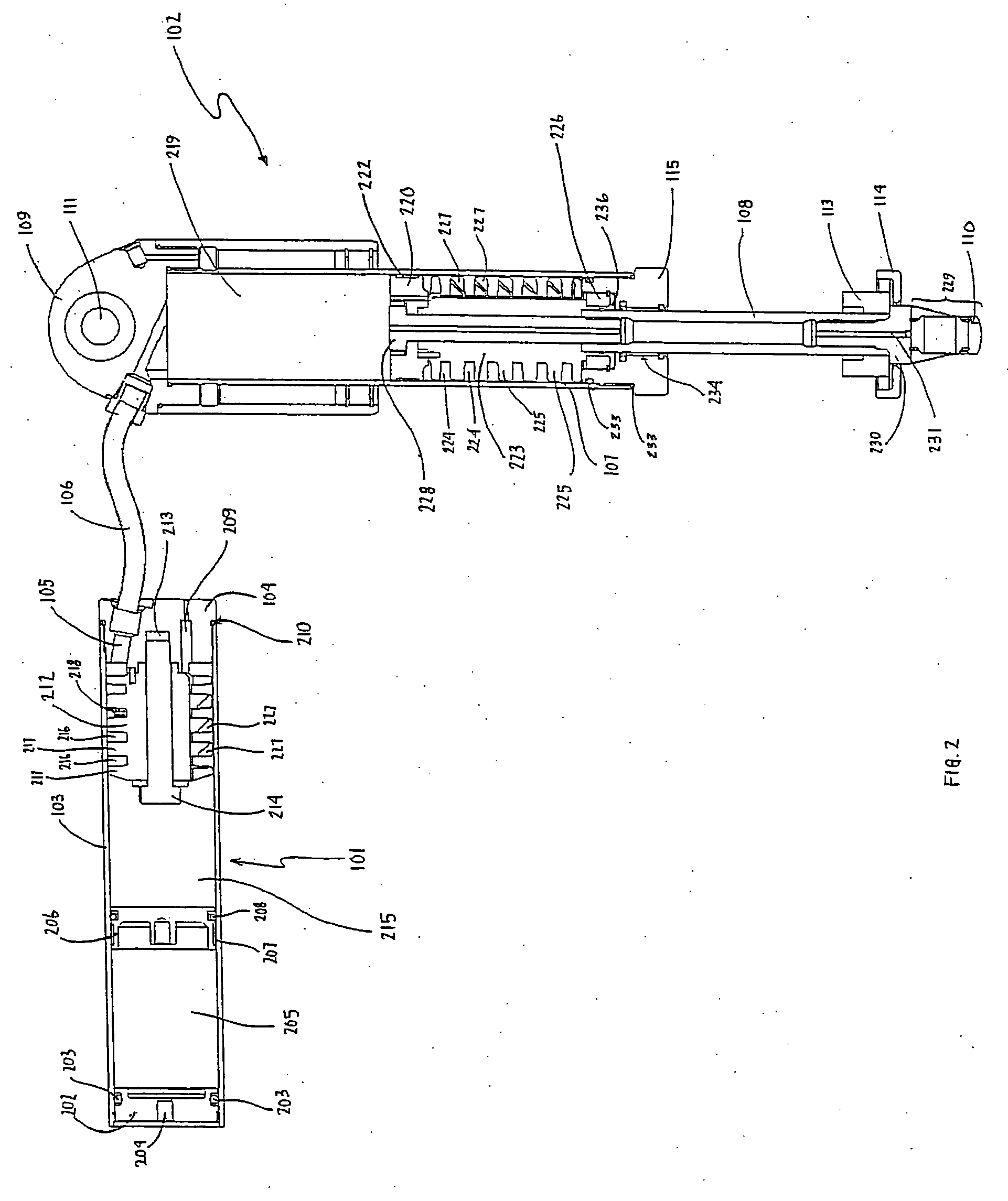
[0043] With reference to FIG. 1, an MR damper system 100 of the present invention is shown and includes a separate reservoir 101 component in communication with a MR damper 102. However, the reservoir 101 may be integral with the MR damper 102 as shown in FIG. 4 where the reservoir 101 is depicted as being contained within the same structure of the MR damper 102. As will be discussed in greater detail below, the reservoir 101 serves to store and return MR fluid (not shown) that has been displaced from the MR damper 102 during compression of the damper 102 a...


PUM


Abstract

A magnetorheological damper system comprising a reservoir in communication with a damper. The damper comprises a damper cylinder defining a damper chamber, wherein the damper chamber contains a magnetorheological fluid and a movable damper piston. The damper piston comprises at least two coil windings on the outer surface of the damper piston, wherein the damper piston is capable of generating a magnetic field between the damper piston and a wall of the damper cylinder. The reservoir comprises a reservoir cylinder defining a passageway, wherein the reservoir includes a magnetorheological electromagnet capable of generating a magnetic field between the magnetorheological piston and a wall of the passageway. The combination of the an MR reservoir and MR damper leads to a damping system capable of damping a wide range of extreme forces.

Description

REFERENCE TO GOVERNMENT [0001] This invention was made with Government support under Contract Nos. DAAE07-00-C-L010 and DAAE07-01-C-L018 awarded by the United States Army. The Government has certain rights in this invention.BACKGROUND OF THE INVENTION [0002] One of the persistent design constraints in the field of engineering is vibration and / or force impact and / or fatigue management. That is, nearly all engineered devices and systems must embody a design that is sufficiently robust so as to safely survive all movement, vibration, impact, etc. that such a device or system is likely to encounter in its useful life. Examples of such areas of engineered devices and systems are seismic protection devices, construction hardware, seating systems in vehicles such as helicopters, boats, etc., manufacturing equipment and the like, all of which relate to the present invention as will be self-evident from the text below that describes in detail various preferred embodiments. [0003] Such design...

Claims


Application Information

Patent Timeline
Patent Type & Authority Applications(United States)
IPC IPC(8): F16F9/53
CPCF16F9/535
Inventor ANDERFAAS, ERIC N.BANKS, DEAN
Owner MILLENWORKS
Why Eureka
Try Eureka