Method of measuring intrinsic resistance of battery and apparatus of same

a technology of intrinsic resistance and measurement method, which is applied in the field of measuring intrinsic resistance of batteries, can solve the problems of low measurement accuracy and achieve the effect of accurately obtaining intrinsic resistan

Inactive Publication Date: 2007-05-31
YAZAKI CORP
View PDF11 Cites 9 Cited by
  • Summary
  • Abstract
  • Description
  • Claims
  • Application Information

AI Technical Summary

Benefits of technology

[0015] The two relational expressions comprise: the first relational expression given by equating the intrinsic resistance to the formula of {(the period of time between the start of discharge and the intrinsic maximum polarization time) / (the period of time between the start of discharge and the tentative maximum polarization time)}×(the maximum value in the range of the intrinsic resistance)+{(the period of time between the intrinsic maximum polarization time and the tentative maximum polarization time) / (the period of time between the start of discharge and the tentative maximum polarization time)}×(the minimum value in the range of the intrinsic resistance); and the second relational expression given by equating the intrinsic resistance to the formula of the differential equation of the second approximate expression substituted the discharge current with the current of the formula of (the peak current)×{(the period of time between the intrinsic and tentative maximum polarization times) / (the period of time between the peak current time and the tentative maximum polarization time). Accordingly, the intrinsic resistance is accurately obtained.
[0019] Accordingly, the difference between the intrinsic resistance and tentative intrinsic resistance becomes small.

Problems solved by technology

Then, the measurement of the intrinsic resistance of the battery at the low rate discharge as described in JP,2003-115331,A does not give high measurement accuracy.

Method used


Image

  • Method of measuring intrinsic resistance of battery and apparatus of same
  • Method of measuring intrinsic resistance of battery and apparatus of same
  • Method of measuring intrinsic resistance of battery and apparatus of same

Examples


Embodiment Construction

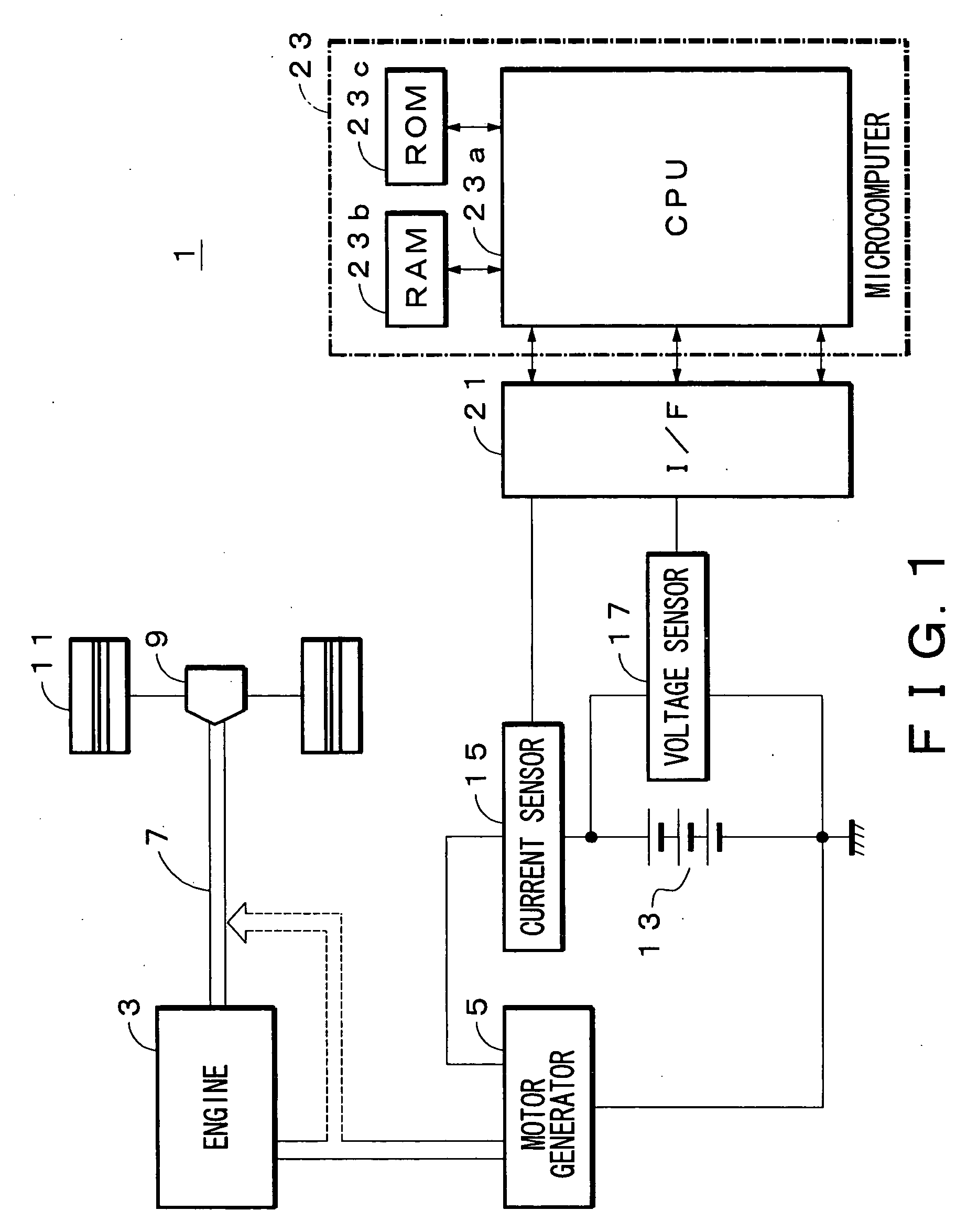
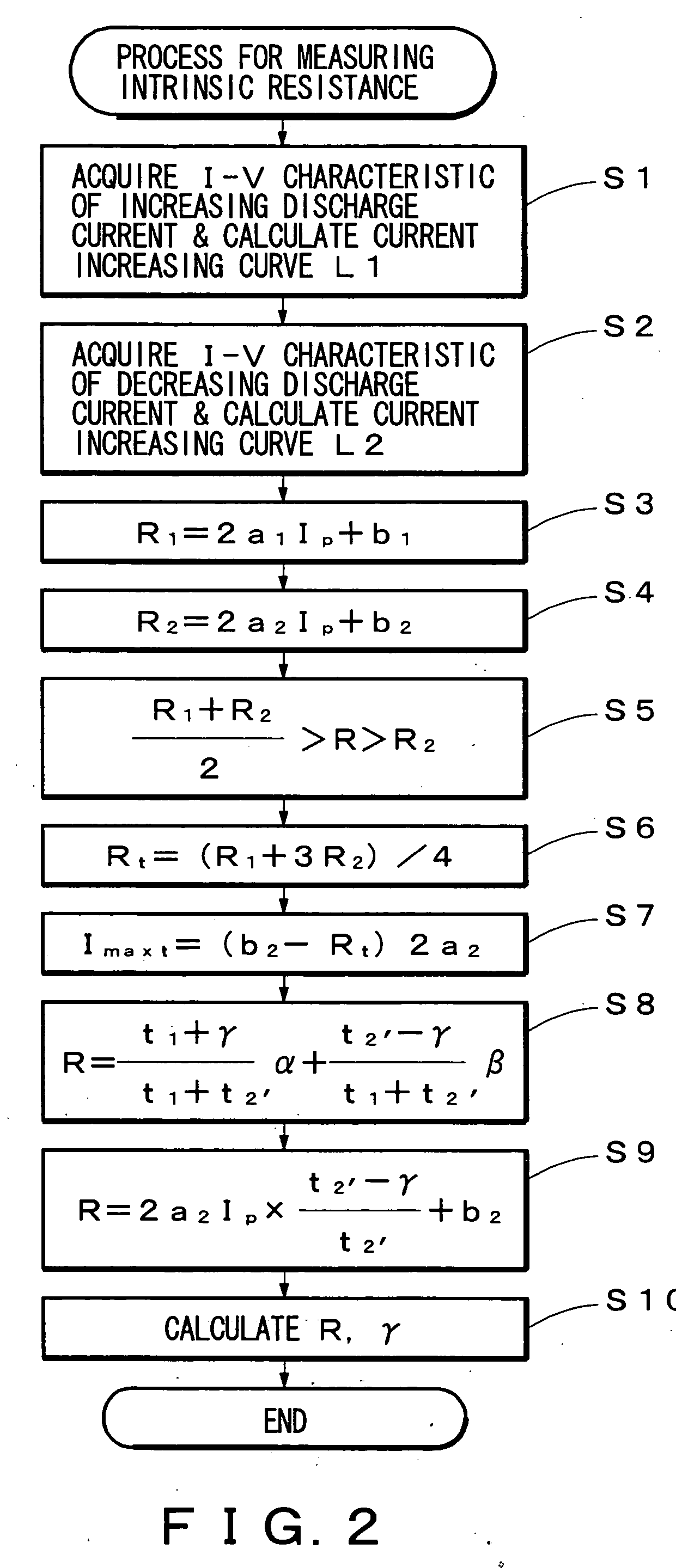
[0030]FIGS. 1 and 2 show an apparatus of measuring an intrinsic resistance of a battery of the present invention. A method of the measurement is explained by referring to FIGS. 3-5.

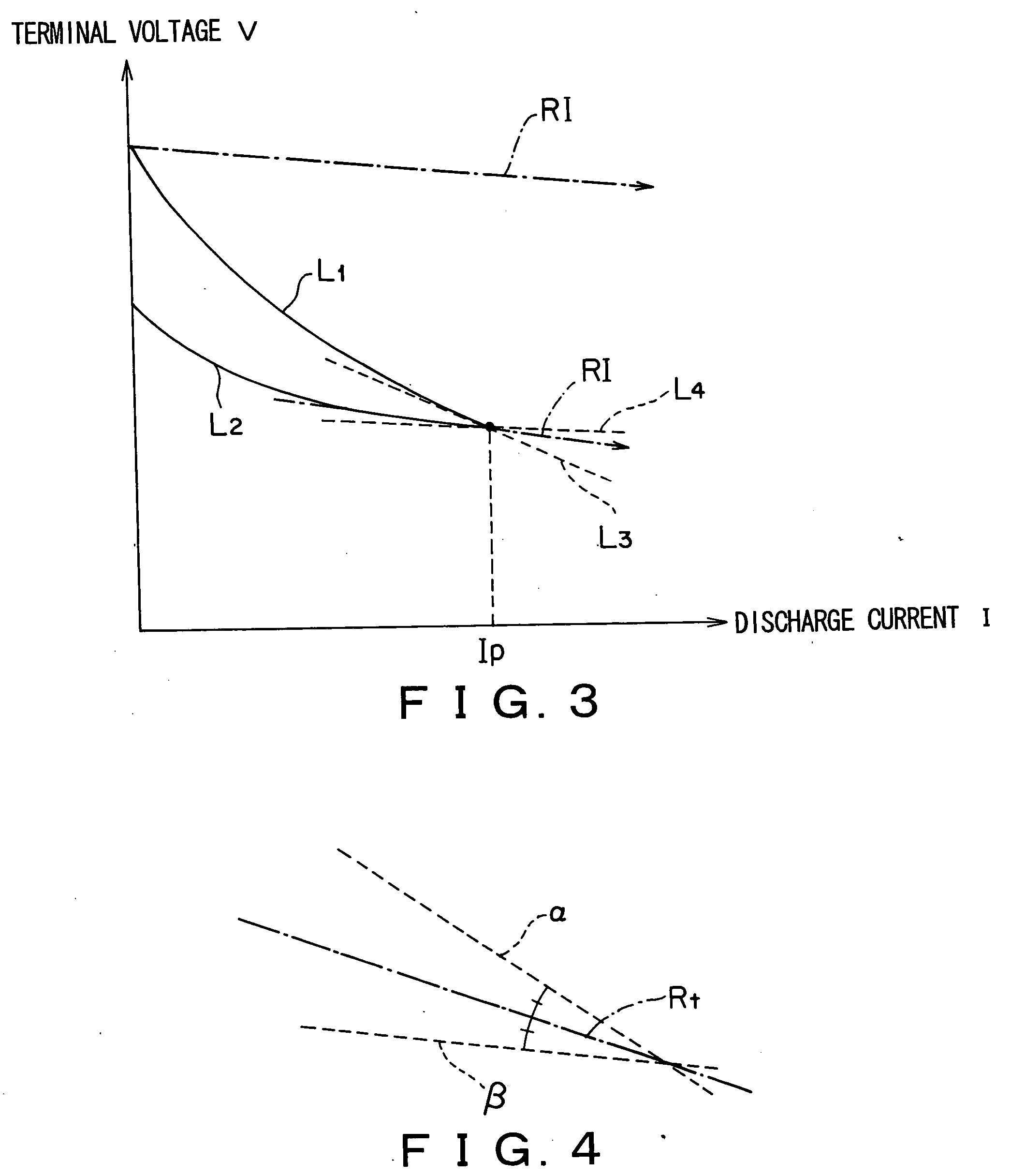
[0031] A low rate discharge discharges a low discharge current (about 1 C-3 C) for a short period of time for a hour rate capacity of the battery. At the low rate discharge, the discharge current increases monotonically from zero to a peak value and decreases in a short period of time and reaches to a steady value corresponding to a load. In the low rate discharge, a concentration polarization reaches to a maximum value prior to the termination of the discharge as shown in FIG. 6B.

[0032] The discharge current and terminal voltage of the battery are measured every a certain period of time at the low rate discharge with increasing and decreasing discharge currents. The measured pairs of the discharge currents I and terminal voltages V are fitted into quadratic approximate expressions of

V=a1I2+b1I+c1 (a c...


PUM


Abstract

The present invention provides a method of measuring an intrinsic resistance of a battery at a low rate discharge and an apparatus of the same. A method of measuring an intrinsic resistance of a battery includes the steps of: measuring periodically a discharge current and a terminal voltage responding to the discharge current at a low rate discharge of the battery; determining a first approximate expression of the terminal voltage with respect to the increasing discharge current and a second approximate expression of the terminal voltage with respect to the decreasing discharge current based on the measured discharge current and terminal voltage; defining a range of the intrinsic resistance based on the first and second approximate expressions; assuming a resistance in the range of the intrinsic resistance as a tentative intrinsic resistance; determining a tentative maximum polarization time from the second approximate expression and the tentative intrinsic resistance; and determining the intrinsic resistance from two relational expressions including the intrinsic resistance, an intrinsic maximum polarization time and the tentative maximum polarization time.

Description

TECHNICAL FIELD [0001] The present invention relates to a method of measuring an intrinsic resistance of a battery which supplies electric power to loads of a vehicle, and an apparatus of the same. RELATED ART [0002] When an engine of a vehicle is started with a starter, an inrush current flows through the starter. The inrush current has a very high current with a short period of time compared with a steady current. [0003] The short period of time means that a polarization can be well correlated with a discharge current. The high current means that the polarization can be reliably determined with accuracy of voltage and current. In the case of a lead battery, the short period of time means at most 400 msec and the inrush current is at least 3 C. [0004] JP,2003-115331,A discloses a method of measuring an intrinsic resistance of a battery at a high rate discharge of the inrush current. [0005] The method is explained by referring to FIGS. 6 and 7. As shown in FIG. 6A, when a high rate ...

Claims


Application Information

Patent Timeline
Patent Type & Authority Applications(United States)
IPC IPC(8): H02J7/00G01R31/36
CPCG01R31/3648G01R31/3662G01R31/389
Inventor ARAI, YOUICHI
Owner YAZAKI CORP
Why Eureka
Try Eureka