Method for material property monitoring with perforated, surface mounted sensors

a surface mounted sensor and material property technology, applied in the direction of magnetic property measurement, material magnetic variables, instruments, etc., can solve the problems of increasing complexity and continuing high priority problems, escalating costs, and accumulation of fatigue damage in critical structural members of aging aircraft, so as to improve the depth of sensitivity, eliminate many undesired behaviors, and promote accurate modeling of the response

Inactive Publication Date: 2007-05-31
JENTEK SENSORS
View PDF31 Cites 16 Cited by
  • Summary
  • Abstract
  • Description
  • Claims
  • Application Information

AI Technical Summary

Benefits of technology

[0016] Aspects of the inventions described herein involve novel inductive sensors for the measurement of the near surface properties of conducting and magnetic materials. These sensors use novel winding geometries that promote accurate modeling of the response, eliminate many of the undesired behavior in the response of the sensing elements in existing sensors, provide increased depth of sensitivity by eliminating the coupling of spatial magnetic field modes that do not penetrate deep into the material under test (MUT), and provide enhanced sensitivity for crack detection, localization, crack orientation, and length characterization. The focus is specifically on material characterization and also the detection and monitoring of precrack fatigue damage, as well as detection and monitoring of cracks, and other material degradation from testing or service exposure.
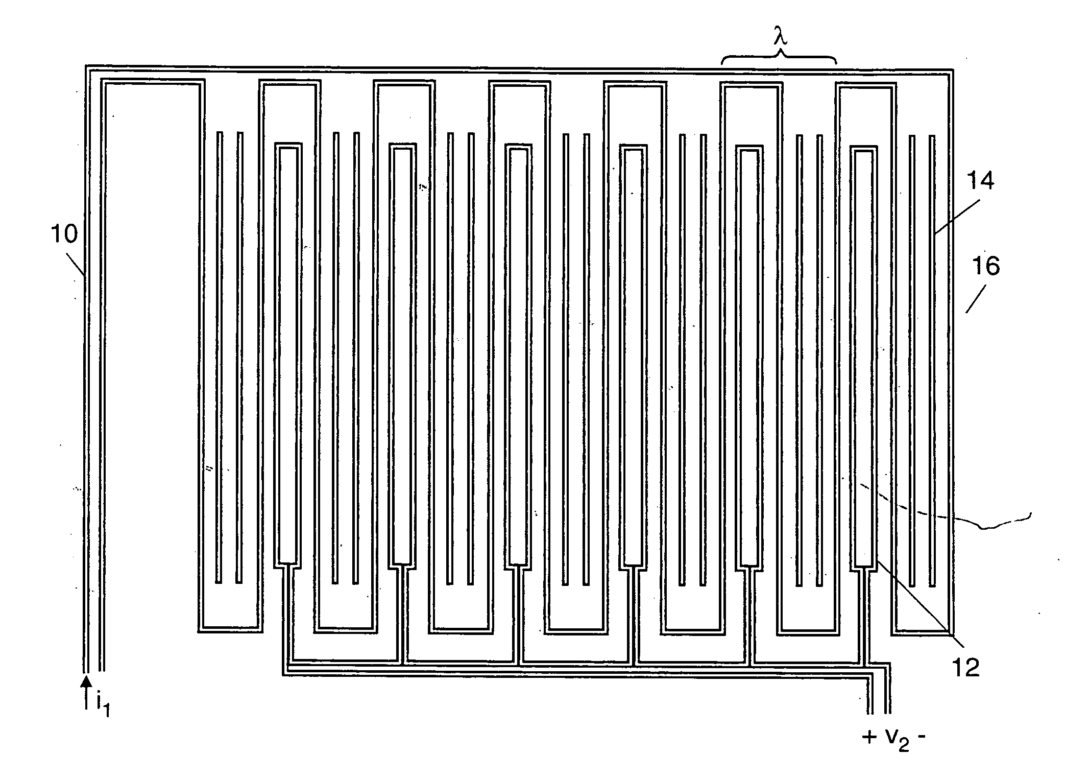
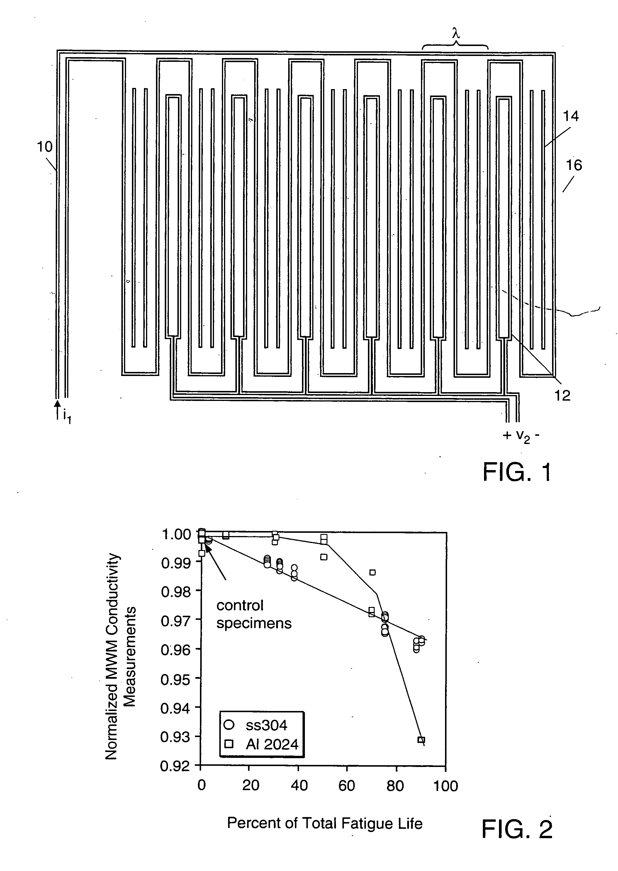
[0019] Novel inspection methods are described herein that relate to new surface mountable eddy-current sensors. These thin, conformable sensors can be mounted on conducting or magnetic materials, metals for example, and used to monitor crack initiation and growth by periodically measuring the sensor response to the material properties beneath the sensor footprint. Spatially periodic field eddy-current sensors, such as the Meandering Winding Magnetometer (MWM), can provide absolute properties measurements using single sensing elements or arrays of sensing elements (MWM-Arrays) located throughout the primary winding meanders. In one embodiment, one of the sensing elements in an array of sensing elements can be located in a place of minimal damage and can be used a reference for the measurement. The change in the electrical property exceeding the background noise level can also be used as an indicator for substantial changes in the MUT condition. In another embodiment, one of the elements can be left in “air” so that an “air” measurement can be used as the reference. In another embodiment of this method, the temperature of the MUT can be varied as a method of verifying the response of the individual sensing elements. The sensing elements can also be calibrated from the measured responses at several temperature levels and knowledge of the temperature dependence of the MUT properties. Alternatively, the use of a temperature sensor can allow the measurements to be compensated for temperature variations. While windings are typically used as the sensing elements, to provide an absolute or differential measurement of the material properties, other embodiments include the use of magnetoresistive elements and SQUIDS.
[0020] In another embodiment, the capability of a spatially periodic field eddy current sensor to provide reliable measurements with a sufficiently large gap (stand off) between the surfaces also provides the capability to monitor initiation of stress corrosion cracking and propagation of stress corrosion cracks. The MWM sensor or MWM-Arrays should not modify the environment that is causing the stress corrosion cracking and, for example, do not create tight crevices between the monitored surface and the MWM. Additionally, in one embodiment the substrate of the MWM sensor perforated between the windings further minimizes any differences between the bulk environment and the environment in the gap between the MWM and the measured surface. Also, in another embodiment a deep penetration surface mounted MWM or MWM-Array can be mounted on the inside skin to monitor hidden corrosion or cracking on the opposite side of the skin. For example, second or third layer corrosion and cracking can be monitored with an MWM-Array mounted on the inside of the third layer. Guides or conduits can be used to permit scanning eddy-current sensors to inspect through the permanently mounted eddy-current sensor. Furthermore, remote actuators can be used to vary the location of the drive and sense windings relative to the MUT.
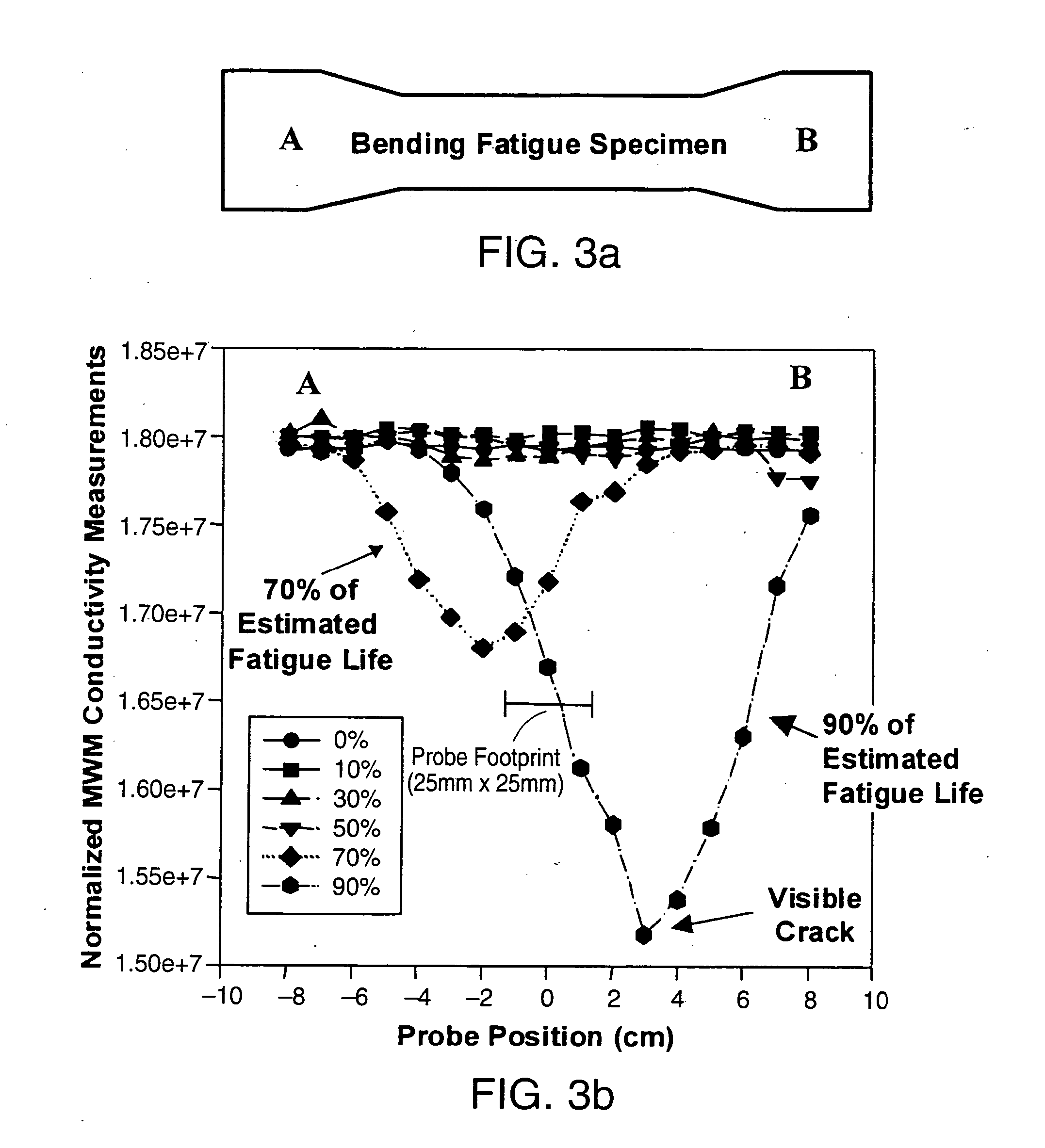
[0022] Methods for characterizing MUT property variations over wide areas. Scanning of spatially periodic field eddy-current sensors over a surface permits the creation of images of the absolute material properties beneath the sensor. Patterns in the images of the properties, such as the electrical conductivity, can indicate locations of damage. Furthermore, multiple frequency or multiple orientation measurements can be used to characterize the damage, such as distinguishing cracks from fretting damage, determining crack size or morphology, detecting hidden corrosion or cracks, determining properties of coating layers, and differentiating damage from manufacturing conditions. The capability to create images of damage allows the extent of the damage to be identified so that the size and type of patches can be determined. For areas of wide-spread or distributed fatigue damage, identifying locations of damage can be used to schedule future inspections or repair and replacement actions. In one embodiment, the flexible sensor can be mounted to a compliant layer that is affixed to a substrate that approximates the shape of the surface of the MUT. In another embodiment, two or more sensing elements can be situated to pass over the same flaw with a single scan. The signals from the individual sensing elements can then be processed and combined to enhance the flaw signal.

Problems solved by technology

This requires increased inspection, maintenance, and repair of aircraft components, which also leads to escalating costs.
The corresponding accumulation of fatigue damage in critical structural members of these aging aircraft, however, is an increasingly complex and continuing high priority problem.
Many components that were originally designed to last the design life of the aircraft without experiencing cracking (i.e., safe life components) are now failing in service, both because aircraft remain in service beyond original design life and, for military aircraft, because expanded mission requirements expose structures to unanticipated loading scenarios.
New life extension programs and recommended repair and replacement activities are often excessively burdensome because of limitations in technology available today for fatigue detection and assessment.
Managers of the Aircraft Structural Integrity Program (ASIP) are often faced with difficult decisions to either replace components on a fleet-wide basis or introduce costly inspection programs.
Furthermore, there is growing evidence that (1) multiple site damage or multiple element damage may compromise fail safety in older aircraft, and (2) significant fatigue damage, with subsequent formation of cracks, may occur at locations not considered critical in original fatigue evaluations.
In application of damage tolerance, inspection schedules are often overly conservative because of limitations in fatigue detection capability for early stage damage.
Even so, limited inspection reliability has led to numerous commercial and military component failures.
However, there are also numerous examples of components originally designed on a safe-life basis that have failed prior to or near their originally specified design life on both military and commercial aircraft.
For safe-life components that must now be managed by damage tolerance methods, periodic inspections are generally far more costly than for components originally designed with planned inspections.
Often the highest cost is associated with disassembly and surface preparation.
Additionally, readiness of the fleet is directly limited by time out of service and reduced mission envelopes as aircraft age and inspection requirements become more burdensome.
Furthermore, the later an inspection uncovers fatigue damage the more costly and extensive the repair, or the more likely replacement is required.
In these tests, fatigue damage was found to be related to diffraction line broadening.
However, it is generally impractical to make such measurements in the field.
Electrical resistivity also provides a potential indication of cumulative fatigue damage.

Method used


Image

  • Method for material property monitoring with perforated, surface mounted sensors
  • Method for material property monitoring with perforated, surface mounted sensors
  • Method for material property monitoring with perforated, surface mounted sensors

Examples


Embodiment Construction

[0078] A description of preferred embodiments of the invention follows. To safely support life extension for aging structures and to reduce weight and maintenance / inspection costs for new structures requires both rapid and cost effective inspection capabilities. In particular, continuous monitoring of crack initiation and growth requires the permanent mounting of sensors to the component being monitored and severely limits the usefulness of calibration or reference standards, especially when placed in difficult-to-access locations on aging or new structures.

[0079] Permanent and surface mounting of conventional eddy-current sensors is not performed. One reason for this is the calibration requirements for the measurements and another is the variability between probes. Conventional eddy-current techniques require varying the proximity of the sensor (or lift-off) to the test material or reference part by rocking the sensor back and forth or scanning across a surface to configure the eq...


PUM

PropertyMeasurementUnit
diameteraaaaaaaaaa
diameteraaaaaaaaaa
elastic stress concentrationaaaaaaaaaa

Abstract

Material condition monitoring may be performed by electromagnetic sensors and sensor arrays mounted to the material surface. The sensors typically have a periodic winding or electrode structure that creates a periodic sensing field when driven by an electrical signal. The sensors can be thin and flexible so that they conform to the surface of the test material. They can also be mounted such that they do not significantly modify the environmental exposure conditions for the test material, such as by creating stand-off gaps between the sensor and material surface or by perforating the sensor substrate.

Description

RELATED APPLICATIONS [0001] This application is a divisional of U.S. application Ser. No. 10 / 633,905, filed Aug. 4, 2003, which is a divisional of U.S. application Ser. No. 09 / 666,879, filed Sep. 20, 2000, which is a Continuation-in-Part of U.S. application Ser. No. 09 / 656,723 filed Sep. 7, 2000 which claims the benefit of U.S. Provisional Application Nos. 60 / 203,744 filed May 12, 2000, 60 / 155,038 filed Sep. 20, 1999 and U.S. Provisional Application No. 60 / 152,828 filed Sep. 7, 1999; which claims the benefit of U.S. application Ser. No. 09 / 350,502, filed Jul. 9, 1999, now U.S. Pat. No. 6,198,279, which is a Divisional of U.S. application Ser. No. 09 / 122,980 filed Jul. 27, 1998, now U.S. Pat. No. 5,966,011, which is a Divisional of U.S. application Ser. No. 08 / 702,276 filed Aug. 23, 1996, now U.S. Pat. No. 5,793,206 which claims the benefit of U.S. Provisional Application No. 60 / 002,804 filed Aug. 25, 1995; and of U.S. application Ser. No. 09 / 039,190 filed Mar. 13, 1998 which claims ...

Claims


Application Information

Patent Timeline
Patent Type & Authority Applications(United States)
IPC IPC(8): G01N27/82G01B7/24G01B7/34G01N27/90G01R33/12
CPCG01B7/24G01B7/34G01N27/72G01N27/902G01R33/12G01N27/20
Inventor GOLDFINE, NEIL J.SCHLICKER, DARRELL E.WALRATH, KAREN E.WASHABAUGH, ANDREW P.ZILBERSTEIN, VLADIMIR A.TSUKERNIK, VLADIMIR
Owner JENTEK SENSORS
Why Eureka
Try Eureka