Methods for manufacturing and application of RFID built-in cable, and dedicated RFID reading systems

a technology of built-in cables and reading systems, applied in the field of identification of cables, can solve the problems of limited type of most commonly used cables, difficult to distinguish one from another by visual inspection alone, and affecting the quality of printed codes,

Inactive Publication Date: 2007-05-31
HITACHI LTD
View PDF15 Cites 60 Cited by
  • Summary
  • Abstract
  • Description
  • Claims
  • Application Information

AI Technical Summary

Benefits of technology

[0028] This invention can provide a cable identifying system used with RFID built-in cable including therein RFID tags, capable of identifying an target cable accurately over a long period of time without such an operation as writing information into the RFID tags by a cable layer or user; a method for fabricating the cable identifying system; a method for application of the cable identifying system; and an RFID reader dedicated to the RFID built-in cable. The cable identifying system is especially effective when it is desired to remove a particular cable among a plurality of cables already laid out and to identify the particular cable which has both its ends unable to be identified.

Problems solved by technology

Most often used cables, however, are limited in their type, that is, only several types of cables are preferably used in most applications.
They look all alike and therefore it is difficult to distinguish one from another by visual inspection alone.
Surface printing has a problem that the printed codes are subjected to abrasion or smearing during handling of cable in its layout operations.
Tagging is risky in that tags may be torn off the cable during laying work, and also has a problem that since tagging is more laborious than printing, the provision of cable with tags at regular intervals for facility of identification will cause an increase in cost as the length of cable increases.
These cable structures still have room for improvement in that somewhat laborious work is necessary to record such information as names in the information storage elements whose number increases in proportion as the length of cable increases.

Method used


Image

  • Methods for manufacturing and application of RFID built-in cable, and dedicated RFID reading systems
  • Methods for manufacturing and application of RFID built-in cable, and dedicated RFID reading systems
  • Methods for manufacturing and application of RFID built-in cable, and dedicated RFID reading systems

Examples


Embodiment Construction

[0041] Embodiments of this invention will now be described with reference to the attached drawings.

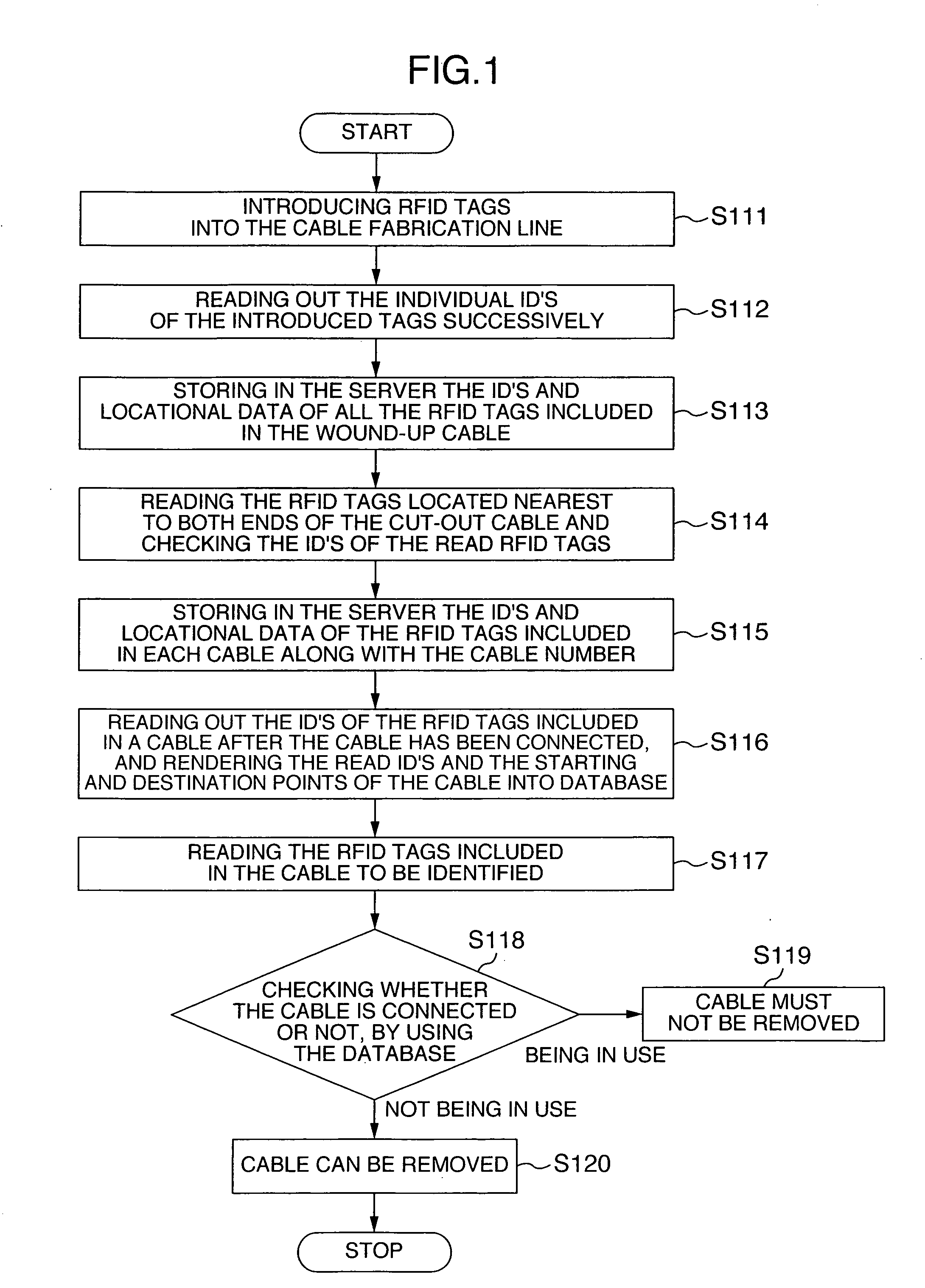
[0042]FIG. 1 is a flow chart illustrating how a cable identifying system used with RFID built-in cable according to this invention, is operated.

[0043] Individual steps will be described in detail in the following.

[0044] RFID tags are first introduced in a cable fabricating line (step 111) and the individual ID's of the introduced RFID tags are then read out successively (step 112).

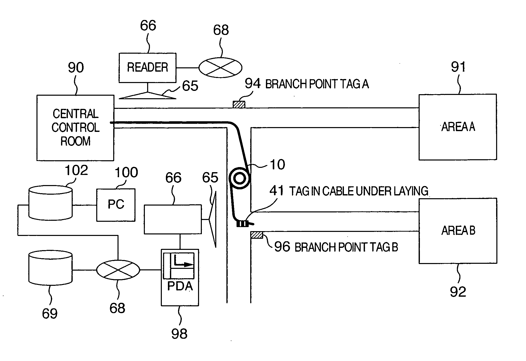
[0045] Structural examples of a cable having RFID tags built therein, used in this invention will be described with reference to FIGS. 4, 5A and 5B.

[0046] In order to attach RFID tags onto a cable to be fabricated, RFID tags 41 are attached onto the internal structure of the cable before the last stage of cable fabricating process wherein sheath serving as the outermost layer of the cable is fabricated. For example, RFID tags may be directly stuck onto the insulation resin layer 43 of strand wires (condu...


PUM


Abstract

Disclosed is a cable identifying system for accurately discriminating one cable from another on site over a long period of time, the system enabling a cable layer or a cable user, when laying out an RFID built-in cable, to do without manually writing any information in the RFID tags built in the cable. One cable having RFID tags built therein can be accurately realized. The individual ID's of the RFID tags are read and stored in a storage apparatus. When a part of the cable is cut, the ID's of the RFID tags nearest to the both end of the cable are read out, and the ID-related data of the RFID tags in the cut-out cable are recorded on a desired medium or electronic information medium.

Description

INCORPORATION BY REFERENCE [0001] The present application claims priority from Japanese application JP 2005-333519 filed on Nov. 18, 2005, the content of which is hereby incorporated by reference into this application. FIELD OF THE INVENTION [0002] This invention relates to the identification of cables; and more particularly to a system for discriminating one cable from another, the cable including therein RFID tags incorporating therein information memory devices storing therein the location data of the tags; methods for manufacture and application of the system; and an RFID reader dedicated to the RFID built-in cable. BACKGROUND OF THE INVENTION [0003] The RFID (radio frequency identification) technique that has recently been developed rapidly is a system wherein a radio transmitter / receiver called a reader / writer reads or writes information into or from, tags incorporating therein information memory devices without physical contact. This system, different from the bar-code reader...

Claims


Application Information

Patent Timeline
Patent Type & Authority Applications(United States)
IPC IPC(8): G08B13/14G06F17/00H01R3/00
CPCH01B7/368
Inventor UTAKA, KENJIYOKOTA, TOSHIMISHIGEMI, RYOUSUKEOTA, CHIKARAARAKI, KENJIUESAKA, KOUICHI
Owner HITACHI LTD
Why Eureka
Try Eureka