Plasma display apparatus and method of driving a plasma display panel

a plasma display panel and plasma display technology, applied in the direction of instruments, static indicating devices, etc., can solve the problems of reducing the brightness or resolution of the image displayed by the pdp, and achieve the effects of high brightness, high resolution, and large operating margin

Inactive Publication Date: 2007-05-31
MAXELL HLDG LTD
View PDF37 Cites 5 Cited by
  • Summary
  • Abstract
  • Description
  • Claims
  • Application Information

AI Technical Summary

Benefits of technology

[0014] Thus, it is an object of the present invention to provide an interlace-type PDP having a structure which allows an increase in the operating margin. It is another object of the present invention to provide a method of driving such a PDP with an increased operating margin. It is a still another object of the present invention to provide a method of driving such a PDP to display an image with improved resolution and / or increased brightness.
[0016] By employing the above-described structure for the interlace-type PDP, an improved operating margin can be obtained. However, the provision of the non-discharge gaps each of which is additionally formed between discharge gaps, results in a reduction in brightness or resolution of an image displayed by the PDP. To avoid the above problem, the method of driving the PDP and driving waveforms used to drive the PDP are improved. That is, cells are grouped such that each group includes two or three cells adjacent to one another in a direction crossing the discharge gaps, and cells are turned on or off in units of groups. By simultaneously lighting two cells, brightness and resolution can be improved.
[0017] A structure for an interlace-type PDP having no non-discharge gaps (that is, having only discharge gaps successively disposed) may be modified such that at least one of the electrode structure and the barrier rib structure is improved so as to reduce the coupling between adjacent cells to a desirable low level at which adjacent cells are properly coupled to each other.
[0018] If the above-described improved structure in which there is no non-discharge gap is employed for the interlace-type PDP, the coupling between adjacent cells can be reduced to an optimal low level, and the operating margin can be increased. However, the above-described structure results in a reduction in the brightness of images displayed by the PDP. The above problem can also be overcome by improving the driving method and / or the driving waveform. That is, cells are grouped such that each group includes two or three cells adjacent to one another in a direction crossing the discharge gaps, and cells are turned on or off in units of groups. By simultaneously lighting two cells, brightness can be improved.
[0023] As described above, it is possible to achieve an interlace-type plasma display apparatus having a large operating margin and capable of displaying an image with high resolution and high brightness, by employing one of PDP structure in conjunction with one of driving method or a combination thereof disclosed herein.

Problems solved by technology

However, the provision of the non-discharge gaps each of which is additionally formed between discharge gaps, results in a reduction in brightness or resolution of an image displayed by the PDP.

Method used


Image

  • Plasma display apparatus and method of driving a plasma display panel
  • Plasma display apparatus and method of driving a plasma display panel
  • Plasma display apparatus and method of driving a plasma display panel

Examples


first embodiment

[0088] Referring to FIGS. 4 to 14, a structure of a PDP and a method of driving it, according to a first embodiment of the present invention, are described below.

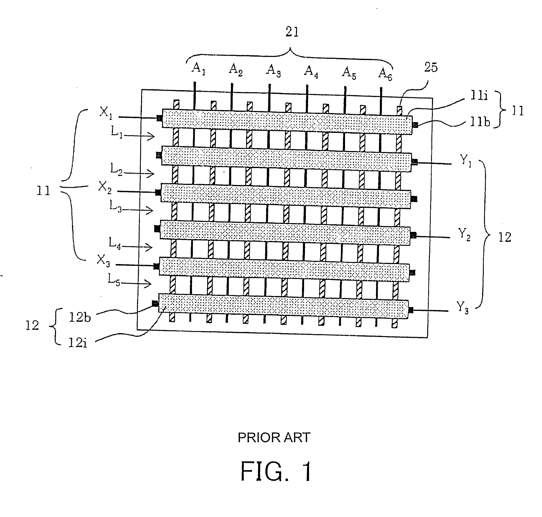
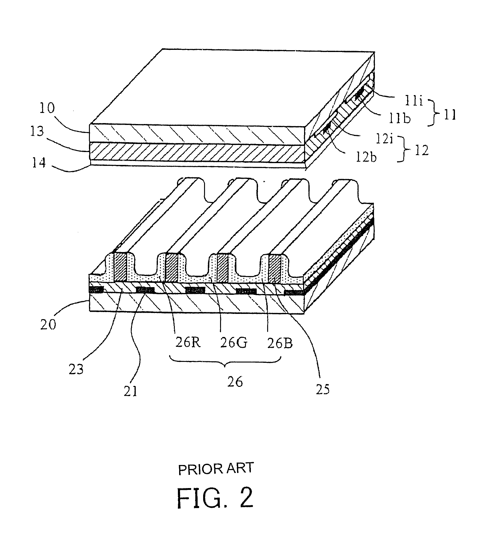
[0089]FIG. 4 is a plan view showing the structure of the PDP according to the first embodiment, and FIG. 5 is an exploded perspective view thereof.

[0090] In FIGS. 4 to 40, X1 to X3 denote display electrode pairs 11, Y1 to Y3 denote scanning electrode pairs 12, and A1 to A6 and 21 (FIG. 5) denote address electrodes. Although rather small numbers of electrode pairs are shown in those figures for the purpose of convenience representation, a practical PDP includes great numbers of electrode pairs. Each of the display electrode pairs 11 and also each of the scanning electrode pairs 12 include two electrodes. In the example shown in FIG. 5, two electrodes 11α and 11β form an electrode pair X1, and two electrodes 12α and 12β form an electrode pair Y1. Each electrode of any electrode pair is formed of a transparent electrode and ...

second embodiment

[0143] The technique disclosed above in the first embodiment can be used to display a high-resolution image of a general pattern. However, when a special pattern is displayed, degradation in resolution can occur. A second embodiment of the present invention provides a driving technique which makes it possible to display a high-resolution image even for such a special pattern.

[0144] First, when such a special pattern is displayed, what occurs with the first embodiment is described with reference to FIGS. 15A, 15B, 16A, 16B and 16C.

[0145]FIGS. 15A and 15B show the method of turning on / off cells according to the first embodiment, in which cells are grouped such that two cells adjacent in the vertical direction to each other are grouped together, and two cells in each group are simultaneously turned on or off, wherein grouping of cells is shifted by one cell in the vertical direction between the frame (as shown in FIG. 15A) and the odd frame (as shown in FIG. 15B).

[0146] When display...

third embodiment

[0222] In the first and second embodiments described above, the driving waveforms used in the display period are opposite in phase between X electrode pairs and Y electrode pairs, while the driving waveforms applied to any X electrode pair are the same in phase and the driving waveforms applied to any Y electrode pair are also the same in phase. This causes the display discharge to occur simultaneously in all cells, which results in a high peak discharge current. This is undesirable from the point of view of the operation margin and also the load imposed on the driver. Furthermore, the large discharge current results in large electromagnetic radiation.

[0223] To avoid the above problems, driving waveforms shown in FIG. 34 are employed. As shown in FIG. 34, four different driving pulses are applied to four types of electrode pairs Xodd, Yodd, Xeven, and Yeven, respectively. For ease of understanding of the locations at which discharges occurs, a driving pulse applied to one additiona...


PUM


Abstract

An interlace-type PDP is driven by an improved driving method so as to achieve a greater operating margin, higher resolution, and higher brightness. The interlace-type PDP is driven using odd and even frames in such a manner that the cells are grouped into cell groups such that each cell group includes two or three cells which are adjacent in a direction crossing the electrode pairs, and the cells are driven in units of cell groups. The grouping of cells is performed differently for even and odd frames such that, in one type of frame, locations of two or three cells grouped into each group are shifted by one cell, in the direction crossing the electrode pairs, from the locations of cells grouped together in the other type of frame.

Description

CROSS-REFERENCE TO RELATED APPLICATIONS [0001] This application is a Continuation of application Ser. No. 10 / 642,180, filed Aug. 18, 2003, allowed, and claims the benefit of Japanese Application No. 2002-253654, filed Aug. 30, 2002 which are incorporated herein by reference. BACKGROUND OF THE INVENTION [0002] 1. Field of the Invention [0003] The present invention relates to a method of driving a plasma display panel and a plasma display apparatus, and more particularly, to improvements in an interlace-type plasma display panel and a technique of driving of a plasma display panel in an interlaced fashion. [0004] 2. Description of the Related Art [0005] A technique of driving, in an interlaced fashion, a plasma display panel (hereinafter referred to as a PDP) is disclosed, for example, in Japanese Unexamined Patent Application Publication No. 9-160525. In this technique disclosed in the patent cited above, X electrodes (display electrodes) and Y electrodes (scanning electrodes) are fo...

Claims


Application Information

Patent Timeline
Patent Type & Authority Applications(United States)
IPC IPC(8): G09G3/28G09G3/288G09G3/20G09G3/291G09G3/292G09G3/293G09G3/294G09G3/296G09G3/298G09G3/299
CPCG09G3/2022G09G2330/08G09G3/294G09G3/2983G09G3/2986G09G3/299G09G2300/0426G09G2310/021G09G2310/0218G09G2310/0224G09G2310/04G09G2310/066G09G2320/0209G09G2320/0228G09G2330/025G09G2330/06G09G3/2932G09G3/291G09G3/296
Inventor HASHIMOTO, YASUNOBUINOUE, HAJIMESEO, YOSHIHOITOKAWA, NAOKI
Owner MAXELL HLDG LTD
Why Eureka
Try Eureka