
Display unit and portable device provided with the same

Inactive Publication Date: 2007-05-31
NEC CORP
View PDF2 Cites 21 Cited by
  • Summary
  • Abstract
  • Description
  • Claims
  • Application Information

AI Technical Summary

Benefits of technology

[0018] In the present invention, transmitting the first signal and the second signal via the common signal line makes it possible to decrease the number of the signal lines.
[0023] It is desirable that the display unit further comprises a storage section for storing the electric power data and that the control section reads the electric power data from the storage section based on the input information, and thereby generates the first signal. Thus, the emission intensity of each illuminant can be easily adjusted.
[0030] According to the present invention, in the display unit capable of performing the color display, it is possible to decrease the number of the signal lines by transmitting the first and second signals via the common signal line.

Problems solved by technology

For this reason, there is a problem that the color of the white color display cannot easily be adjusted.
The above-mentioned conventional technique, however, has problems as described hereinbelow.
For this reason, a circuit area required for arranging the signal lines becomes wide, resulting in an increase in size of the liquid crystal display unit.
Moreover, if trying to prevent an increase in size, a narrow-pitch or multilayered circuit board is consequently required, resulting in an increase in cost of the unit.
For this reason, the circuit area required for arranging the signal lines becomes wide, resulting in an increase in size and cost of the unit.

Method used


Image

  • Display unit and portable device provided with the same
  • Display unit and portable device provided with the same
  • Display unit and portable device provided with the same

Examples


first embodiment

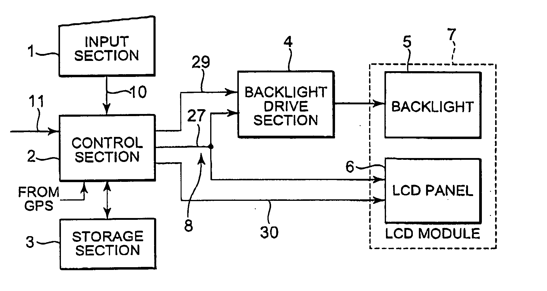
[0049] As shown in FIG. 5, the liquid crystal display unit is generally comprised of five blocks, namely, an input section 1, a control section 2, a storage section 3, a backlight drive section (drive section) 4, and an LCD module 7. The LCD module 7 is comprised of a backlight 5 and an LCD panel 6.

[0050] The input section 1 is a circuit for receiving input information 10 from a key (not shown) provided on the portable device and subsequently outputting the input information 10 to the control section 2. The control section 2 reads LED electric current data stored in the storage section 3 based on the input information 10 inputted from the input section 1 to control the backlight drive section 4, and controls the LCD panel 6 based on the input information 10 and a video signal 11. The storage section 3 includes, for example, a memory, and stores, the LED electric current data (or power data) for representing an electric current value of an LED provided in the backlight 5. The LED el...

third embodiment

[0086] As shown in FIGS. 14 and 15, in the liquid crystal display unit the backlight drive section 4 is provided inside the LCD panel 6. Additionally, the selection signal (third signal) 29 outputted from the control section 2 to the backlight drive section 4 is a serial I / F signal, which is transmitted via a common flexible cable (another common signal line) 13 (refer to FIG. 16) shared with the serial I / F signal of the control signal (fourth signal) 30 outputted to the LCD panel 6 from the control section 2.

[0087] As shown in FIG. 16, in the liquid crystal display unit according to the third embodiment, the flexible cable 13 and a connector 14 are used. One end of the flexible cable 13 is connected to the LCD panel 6, while the other end is connected to the connector 14. The connector 14 is connected to the backlight control section 22 and the LCD panel control section 23 of the control section 2 as shown in FIG. 6. The backlight control section 22 transmits the selection signal ...


PUM


Abstract

A liquid crystal display unit includes a control section. The control section reads LED electric current data stored in a storage section based on input information to control a backlight drive section, and controls an LCD panel based on the input information and a video signal. The backlight drive section provides a backlight with an electric current according to the LED electric current data. The LED electric current data outputted to the backlight drive section from the control section and image data outputted to the LCD panel from the control section are transmitted via a common signal line.

Description

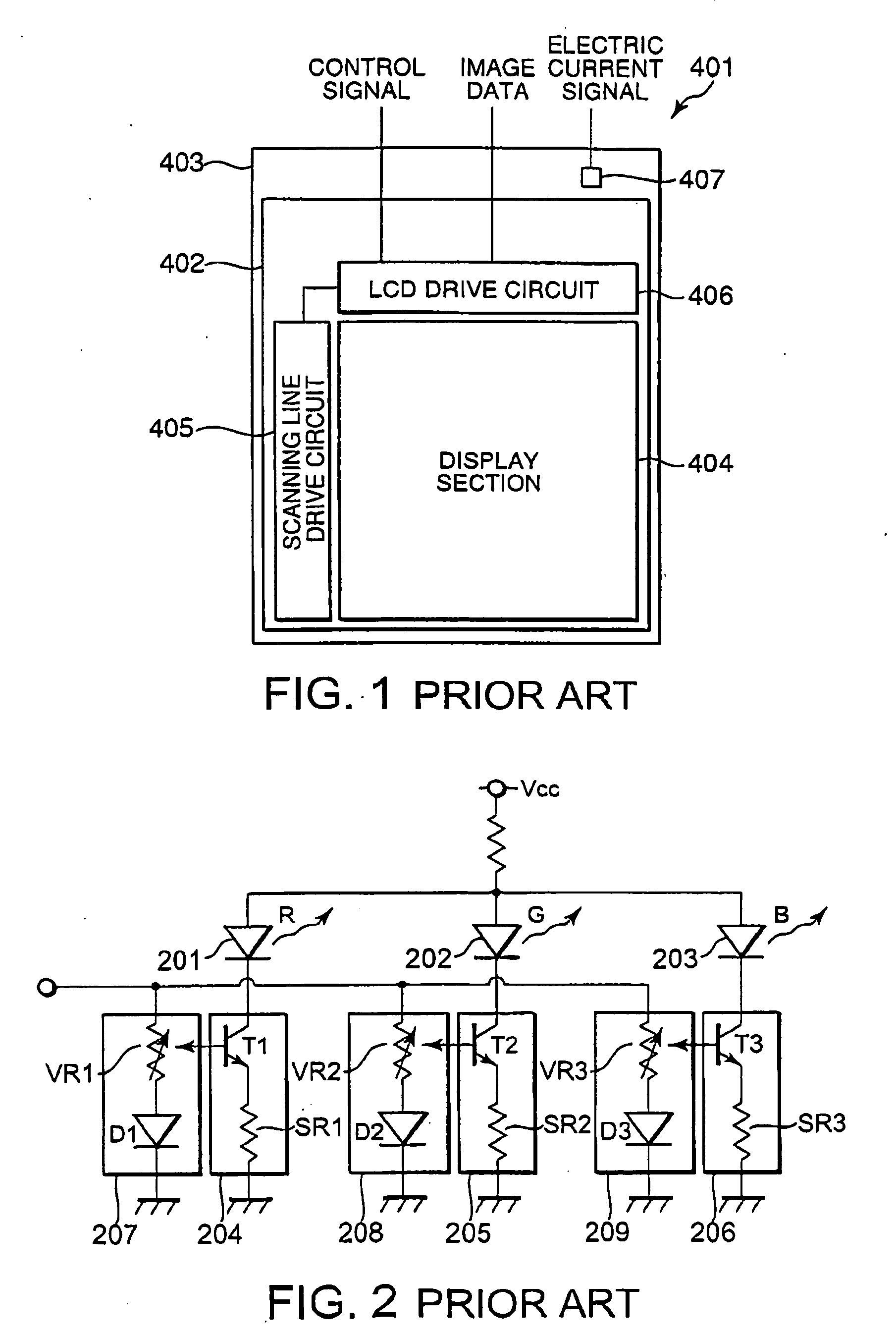
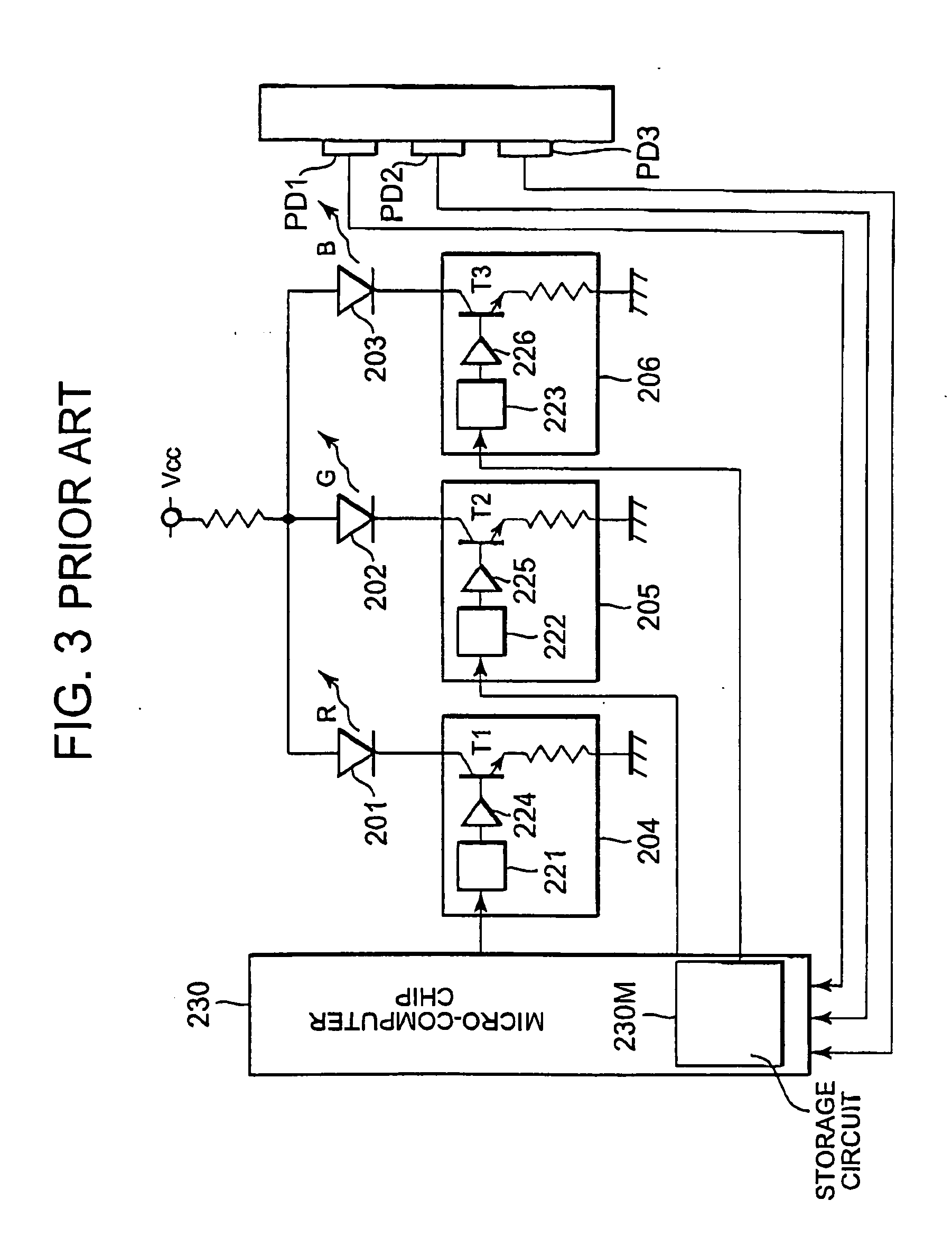
[0001] This application claims priority to prior application JP 2005-153576, the disclosure of which is incorporated herein by reference. BACKGROUND OF THE INVENTION [0002] 1. Field of the Invention [0003] The present invention relates to a color display unit provided with a plurality of illuminants mutually differing in luminous colors, and a portable device provided with the same. [0004] 2. Description of the Related Art [0005] A display unit for displaying a character and an image has widely been mounted on an electronic equipment. FIG. 1 is a block diagram illustrating a conventional liquid crystal display unit. As shown in FIG. 1, a liquid crystal display unit 401 contains an LCD (Liquid Crystal Display) panel 402 for displaying an image. A backlight 403 for providing the LCD panel 402 with a light is provided behind the LCD panel 402. The LCD panel 402 is provided with a display section 404 for displaying the image, a scanning line drive circuit 405 for sequentially scanning a...

Claims


Application Information

Patent Timeline
IPC IPC(8): G09G3/36
CPCG09G3/3413G09G3/3611G09G2320/0606G09G2320/0633G09G2320/0666G09G2320/08G09G2370/04
Inventor SHIMODA, MASAMICHISUZUKI, DAISUKEUCHIKAWA, TATSUYA
Owner NEC CORP
Learn More