Communication apparatus, communication system, image capture apparatus, video capture apparatus, and setting method thereof

a technology of communication apparatus and video capture device, which is applied in the field of communication apparatus, communication system, image capture device, video capture device, etc., can solve problems such as cumbersome procedures

Active Publication Date: 2007-05-31
PANASONIC CORP
View PDF4 Cites 67 Cited by
  • Summary
  • Abstract
  • Description
  • Claims
  • Application Information

AI Technical Summary

Benefits of technology

[0009] Embodiments explained below are provided to address the above-described shortcomings. An object of the embodiments is to provide a communication apparatus, a communication system, an image capture apparatus, a video capture apparatus, and a setting method thereof that allow easy setting between communication apparatuses while requiring no user attention thereto.
[0011] In the configuration above, connecting the another communication apparatus to the electrical outlet automatically performs the negotiation, and thus allows easy setting.
[0014] In the configuration above, connecting the image output apparatus to the power outlet allows easy setting for power line communication. Further, the filter keeps a power line communication signal from flowing to the power input unit, thus enabling high-volume communication with the image output apparatus, without impacting a power line communication network connected via the power input unit.
[0016] In the method above, inserting a plug into a power outlet automatically executes the setting process, and thus allows easy setting.

Problems solved by technology

However, the setting method described in U.S. Patent Publication 2005-132193A1 requires a user to know in advance that the settings are necessary and to press the button on each of the access point and the terminal, thus resulting in cumbersome procedures.

Method used


Image

  • Communication apparatus, communication system, image capture apparatus, video capture apparatus, and setting method thereof
  • Communication apparatus, communication system, image capture apparatus, video capture apparatus, and setting method thereof
  • Communication apparatus, communication system, image capture apparatus, video capture apparatus, and setting method thereof

Examples


first embodiment

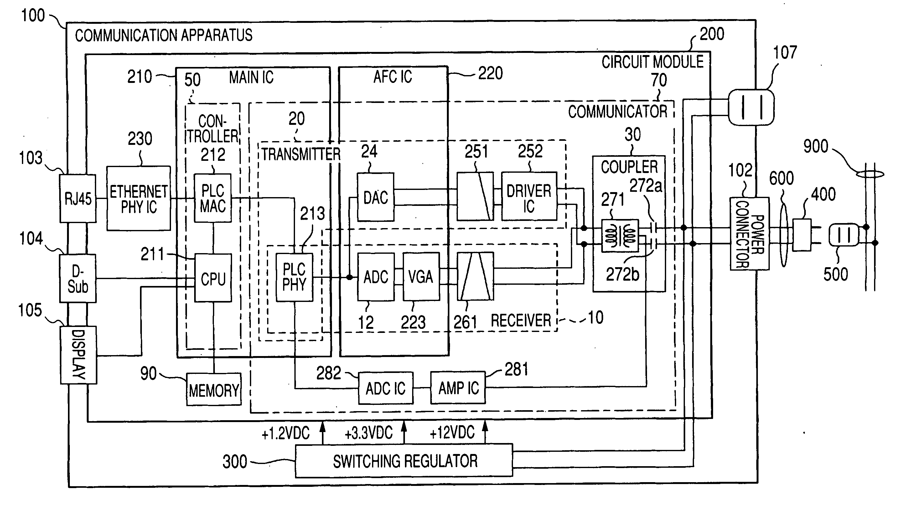
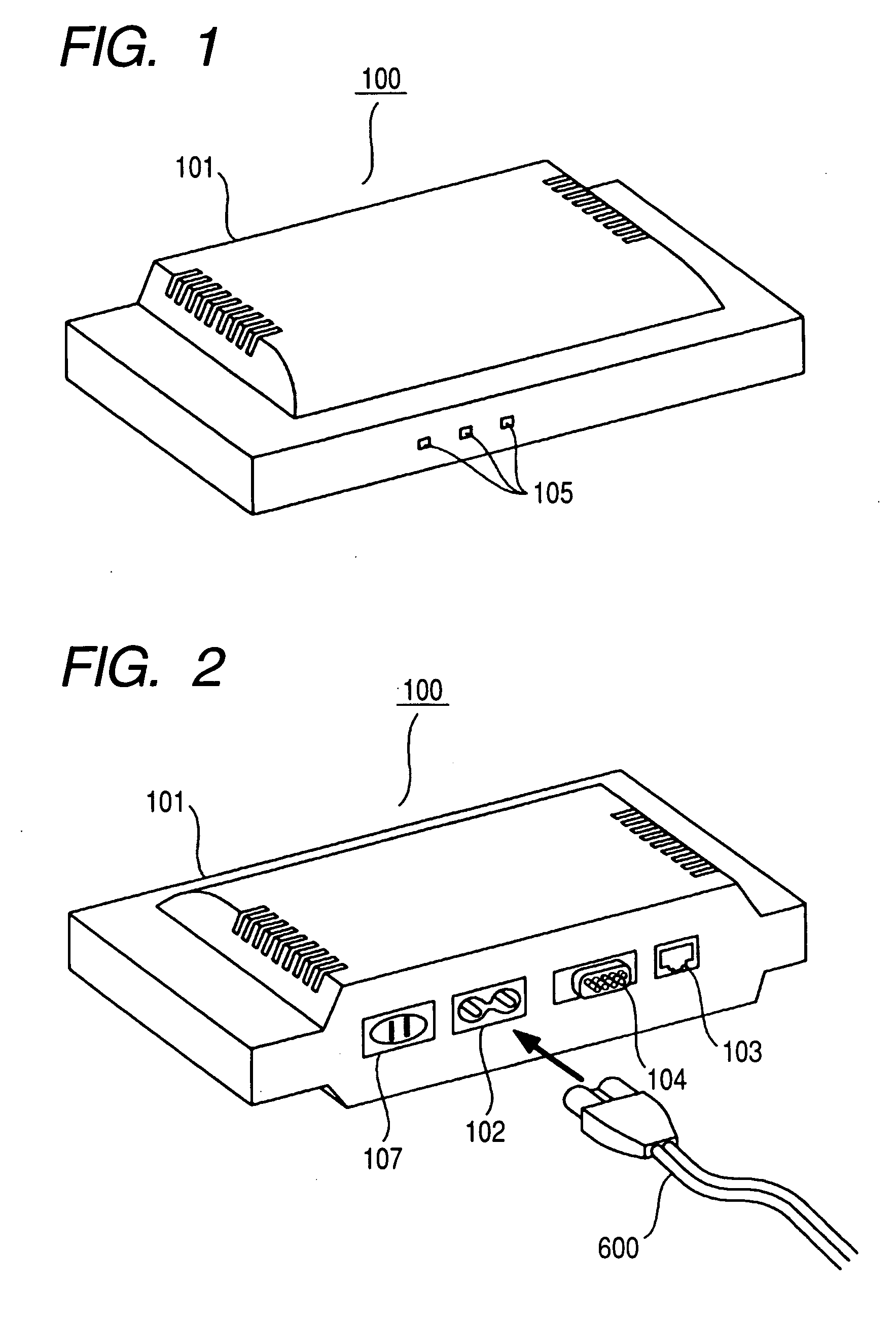
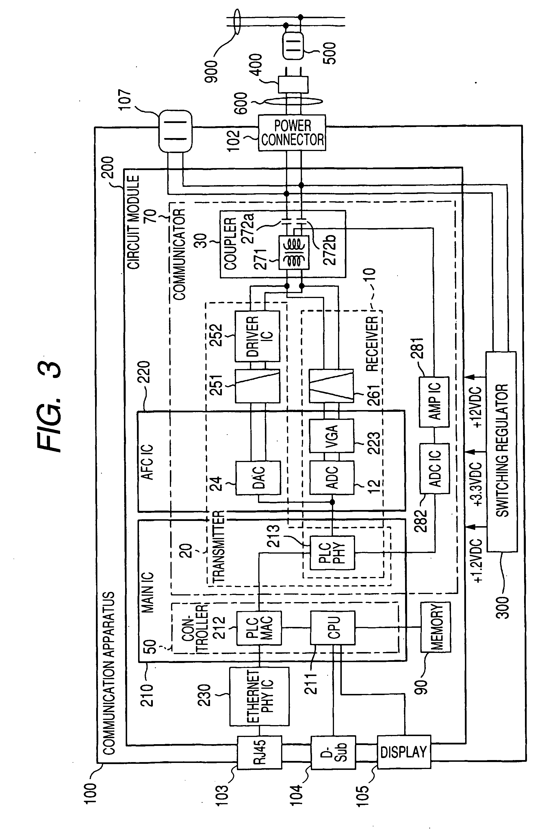
[0069] In FIG. 6, components identical to those in FIG. 3 are provided with identical reference numbers. As shown in FIG. 6, communication apparatus 110 according to a first embodiment has receiver 10, transmitter 20, coupler 30, connection detector 40, controller 50, display 105, and memory 90. Further, communication apparatus 110 includes power connector 102 that functions as an example of the electrical inlet to which power is input and that connects to commercial AC power; and electrical outlet 107 that is electrically connected to power connector 102 and that externally outputs power.

[0070] Receiver 10 has auto gain control circuit (AGC circuit) 11 that functions as an example of an auto gain controller; A / D converter 12; multi-carrier transformer 13 that performs desired time-to-frequency transform, such as a Fourier transformer (FFT), a wavelet transformer (DWT), and the like; equalizer 14 that corrects a received signal so as to cancel an effect of a transmission line; P / S ...

second embodiment

[0102] In FIG. 12, components identical to those in FIG. 1 explained in the first embodiment are provided with identical reference numbers. FIG. 12 shows button 107b provided to electrical outlet 107 as a structure to detect connection of a plug of an external device to electrical outlet 107. Instead of button 107b, however, resistor R shown in FIG. 6 may be provided so that a connection detector monitors a voltage drop at resistor R to detect connection of the plug of the external device.

[0103] As shown in FIG. 12, communication apparatus 120 according to a second embodiment has filter 108, which is inserted between electrical outlet 107 and a power line communication path (a communication path that connects power connector 102 and coupler 30).

[0104] It is desirable that a signal for setting performed via electrical outlet 107 not externally leak from communication apparatus 120 via power connector 102. Further, since a variety of devices other than a communication apparatus can ...

third embodiment

[0117] In FIG. 15, components identical to those in FIG. 3 are provided with identical reference numbers. As shown in FIG. 15, communication apparatus 130 according to the present embodiment has switch (SW) 131, filter 132, and filter selector 133, in addition to the components explained in FIG. 1.

[0118] Switch 131 operates as an example of an instruction input unit that receives an instruction that permits to start a negotiation. Switch 131 receives operation input when the button is pressed, for example, and outputs an instruction to CPU 211. Provided between switch 131 and CPU 211 is a circuit similar to connection detector 40b as shown in FIG. 7B, for example, which allows CPU 211 to detect the pressing of switch 131.

[0119] Filter 132 attenuates a signal in a frequency band that excludes at least an AC power frequency (e.g., 60 Hz). As filter 132, a low pass filter is used, for example, as shown in the drawing. One end of filter 132 is connected to power connector 102, and the...


PUM


Abstract

A communication apparatus has a electrical outlet that is electrically connected to a power connector so as to supply power externally; a connection detector that detects connection of an external plug to the electrical outlet; and a controller that uses a receiver and a transmitter so as to perform setting with a device connected to the electrical outlet, when external connection is detected at the electrical outlet.

Description

BACKGROUND [0001] 1. Field of the Invention [0002] The present invention relates to a communication apparatus, a communication system, an image capture apparatus, a video capture apparatus, and a setting method thereof. [0003] 2. Description of Related Art [0004] To perform wired data communication at home, office, or factory using a terminal, such as a computer, for example, it is normally required to install wiring for cables and connectors used as transmission lines at required locations. A variety of installation works are thus required before starting operation of communication equipment. [0005] Meanwhile, a commercial power source, which is, for example, an AC power of 120 V (60 Hz) in the U.S. or 100 V (50 / 60 Hz) in Japan, is mostly used at home, office, factory, and the like. Thus, power lines that supply the power are already installed across home, office, factory, and the like. Using the power lines for data communication would eliminate additional installation of wiring e...

Claims


Application Information

Patent Timeline
Patent Type & Authority Applications(United States)
IPC IPC(8): H04N7/14
CPCH04B3/54H04B2203/5408H04B2203/5445H04B2203/545H04B2203/5483H04B2203/5491
Inventor KOGA, HISAOKODAMA, NOBUTAKAYOKOMITSU, YASUSHIOOISHI, MUTSUHIKO
Owner PANASONIC CORP
Why Eureka
Try Eureka