Angio capable portable x-ray fluoroscopy unit with sliding c-arm and variable pivot point

a fluoroscopy unit and portable technology, applied in the field of portable x-ray fluoroscopy units with sliding c-shaped arms, can solve the problems of inability to carry heavy equipment without dangerous power-driven operation, large c-arms are difficult to balance, and the device is so bulky that it cannot be used in parallelograms. the effect of improving the efficacy

Active Publication Date: 2007-05-31
GRADY JOHN K
View PDF21 Cites 43 Cited by
  • Summary
  • Abstract
  • Description
  • Claims
  • Application Information

AI Technical Summary

Benefits of technology

[0027] An “Angio Capable Portable X-Ray Fluoroscopy Unit with Sliding C-Arm and Variable Pivot Point” is disclosed. This new Portable C-Arm system keeps the well-known sliding C concept, but improves its efficacy. The novel system overcomes the prior limited range of Portable C-Arm systems by adding a motor driven, variable location of the axle pivot, giving results similar to U.S. Pat. No. 6,789,941 (“Grady '941”), issued Sep. 14, 2004 to the current Applicant, John Grady, but keeping a sliding C-arm mount.

Problems solved by technology

Thus, the entire system is almost twenty feet long, necessitating a twenty-eight or thirty foot long room, which might cause architectural problems.
Because parallelogram-based devices are so bulky, various C-arm based devices have been developed over the years.
However, large C-arms are difficult to balance (e.g., a parallelogram can be an entirely mechanically-balanced device), since the entire mass of the C-shaped structure is offset to one side.
Such devices can deliver most of the angular coverage of a parallelogram in a smaller space, but typically have several severe, inherent problems, such as the inability to carry heavy equipment without dangerous power-driven operation, and if the C-arm slides in the journal, the image will rotate due to an interaction of the two axes.
Some parts of the spherical view become inaccessible.
However, such systems are expensive, and can ultimately degrade the image.
The tilt range of the “sliding C”, and hence the efficacy of the equipment, in that arrangement is unfortunately reduced as the x-ray beam approaches horizontal, as mentioned above.
However, once the C-arm (a.k.a. the “C”) is “slid” in its mount sleeve, the difficulty appears.
These problems led to the “parallelogram” support and positioning apparatus for x-ray equipment disclosed in the Grady '967 patent, mentioned above, issued in 1975 to John K. Grady (the present Applicant) and David B. Rice. That “parallelogram” apparatus has none of the above issues, but obstructs the head of the patient and requires a long room.
However, that obstructs the head end.
It also gives very limited coverage of the patient, as the C-arm radius is limited by the floor and the center point must be inside the patient.
With the recent advent of software based 3-D image reconstructions, the impact of image rotation or shifts is really severe, often becoming a limiting factor in the data integrity.
This prevents effective use of the systems for cardiac angiography, which requires steep angulation in both directions, with a beam close to horizontal.
Having the “grabbing sleeve” right at the horizontal axis will cause packaging problems that conflict with a horizontal beam—the “sleeve” and image tube try to occupy the same space.
However, Applicant soon recognized that the required vertical height of the arc (over 7 feet) and its massive size precluded packaging that equipment, as is, on a portable or wheeled device.

Method used


Image

  • Angio capable portable x-ray fluoroscopy unit with sliding c-arm and variable pivot point
  • Angio capable portable x-ray fluoroscopy unit with sliding c-arm and variable pivot point
  • Angio capable portable x-ray fluoroscopy unit with sliding c-arm and variable pivot point

Examples


Embodiment Construction

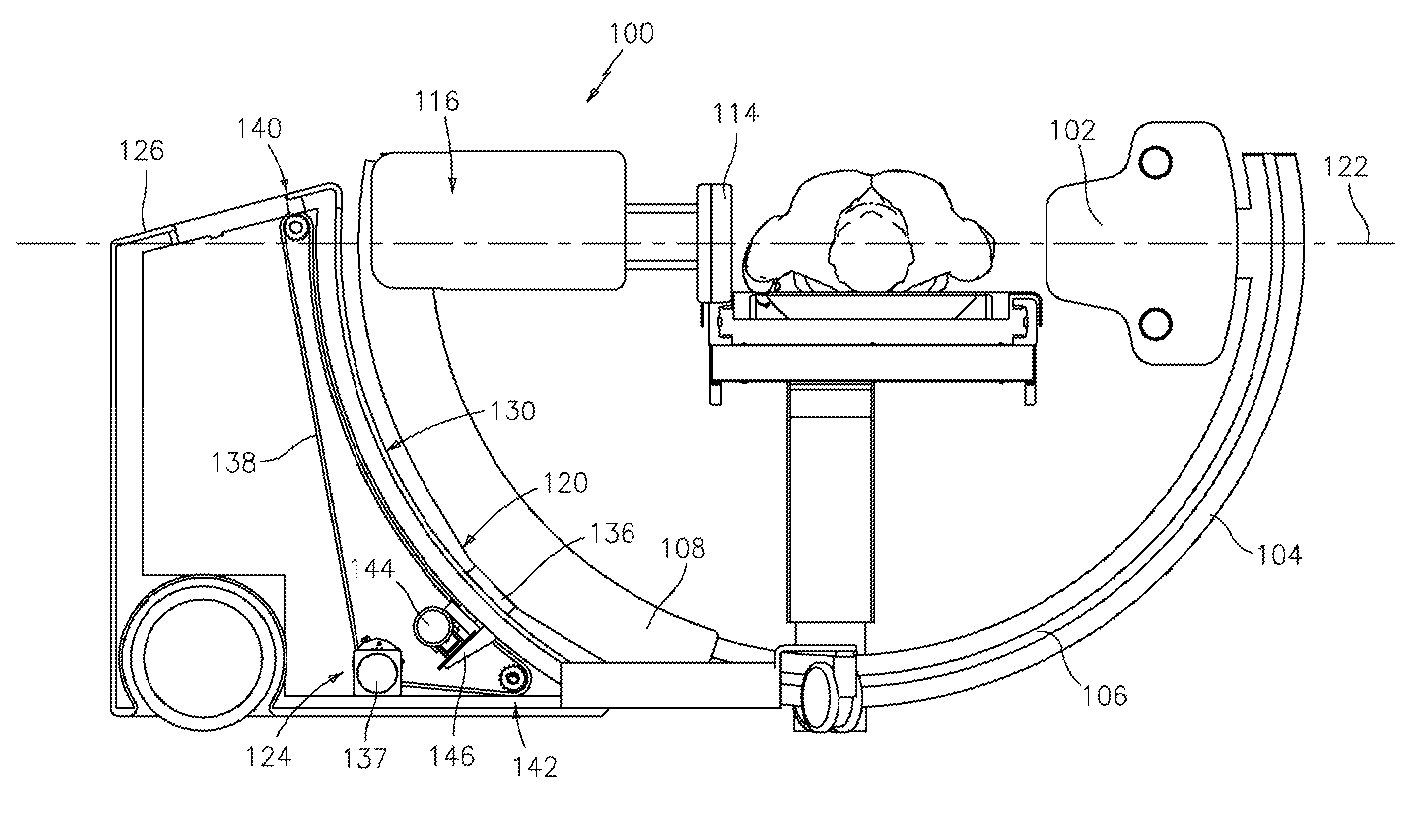
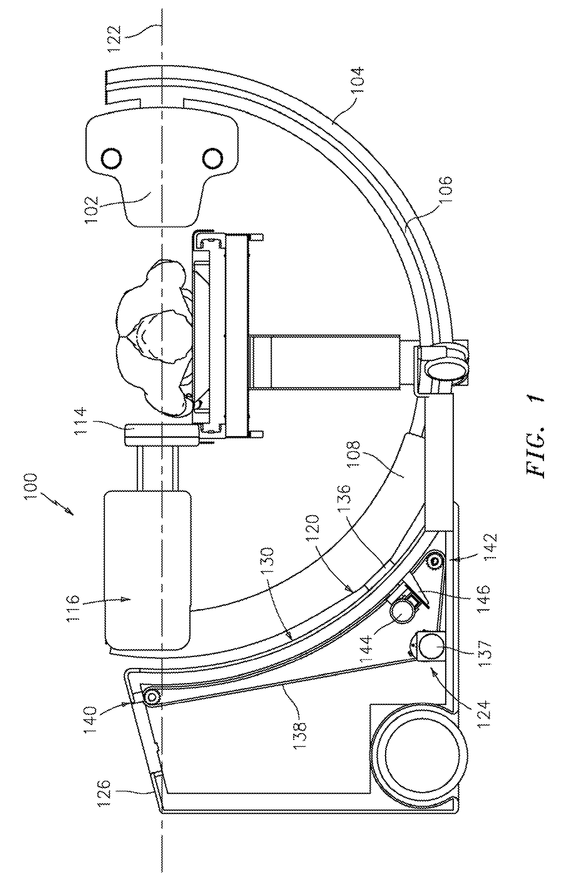
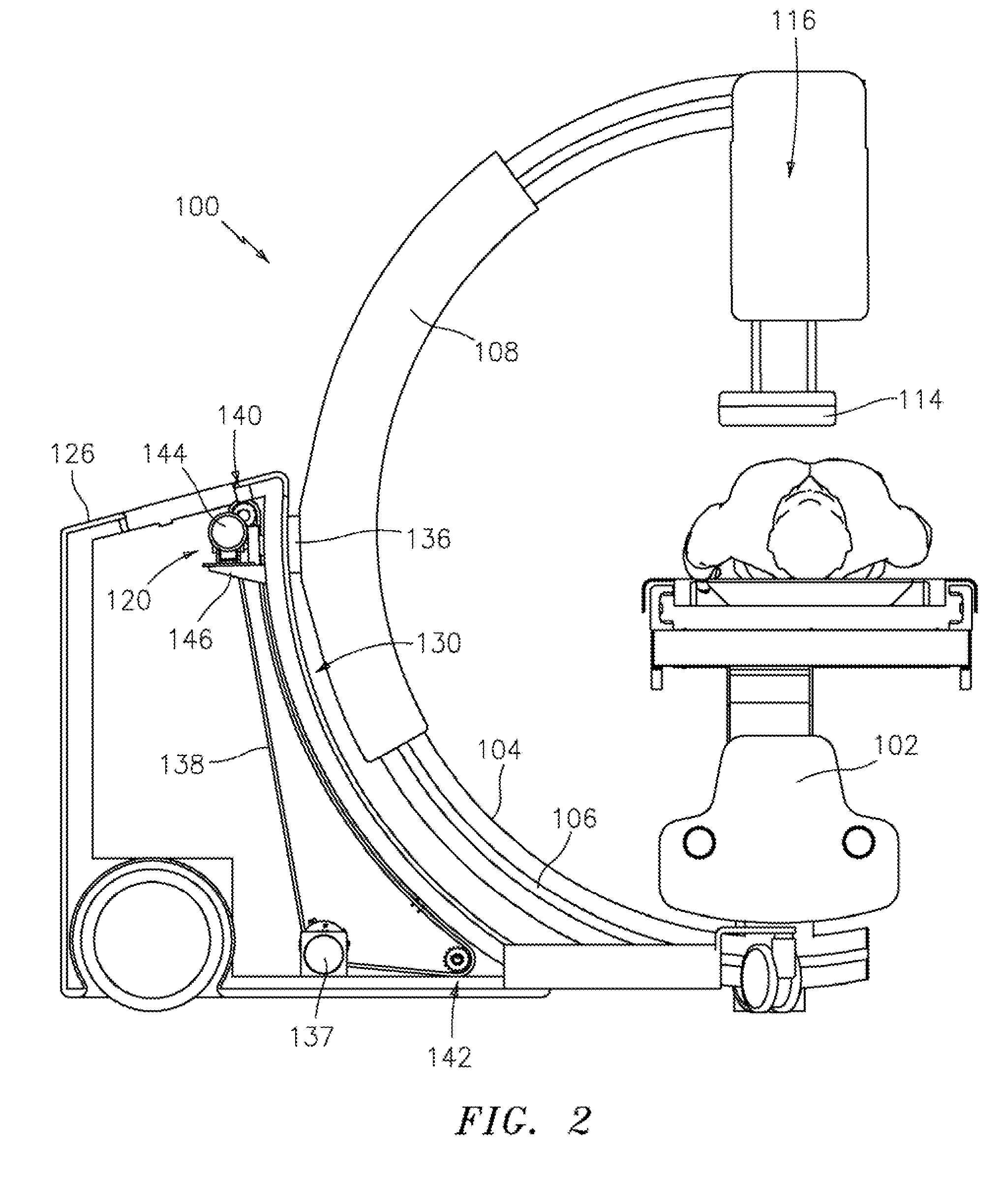
[0037] Referring to FIGS. 1-7, Applicant has disclosed a preferred embodiment of an “Angio Capable Portable X-Ray Fluoroscopy Unit with Sliding C-Arm and Variable Pivot Point.” This new Portable C-Arm system keeps the well-known sliding C concept, but improves its efficacy. The novel system overcomes the prior limited range of Portable C-Arm systems by adding a motor driven, variable location of the axle pivot, but keeping a sliding C-arm mount.

[0038] As with U.S. Pat. No. 6,789,941 (“Grady '941”) issued Sep. 14, 2004 to the current Applicant, John Grady (hereby incorporated by reference), the drawings for Applicant's present embodiment depict a portable C-arm support apparatus 100. The portable C-arm support includes a large radius C-arm (preferably made of carbon fiber) 104 having slide travel rails (e.g., 106) on opposite sides of the C. These slide rails, together with a mid-length of the C-arm 104, can travail within an outer, shorter C-sleeve (a.k.a. “C-slider housing”) 108. ...


PUM


Abstract

An “Angio Capable Portable X-Ray Fluoroscopy Unit with Sliding C-Arm and Variable Pivot Point” is disclosed. It is a new Portable C-Arm x-ray system for fluoroscopy (e.g., angio fluoroscopy) that permits head-to-foot, or cranio-caudal, angulation without appreciable degradation or rotation of the recorded image in the segment of possible views most desired to be used for cardiac angiography, generally between a vertical beam and 60 degrees to the patient's left side from vertical. Applicant's preferred embodiment comprises an portable x-ray device of the type having a C-arm which “slides” through a fixed C-slider housing or sleeve mounted onto a portable base, wherein: the C-slider housing is mounted onto the portable base through a rotatable tilt bearing, and the rotation axis of the bearing and fixed sleeve can be repositioned, within an arcuate slot in the base, from approximately horizontal, when the x-ray beam is vertical, to between approximately 60 degrees and 40 degrees below horizontal in a vertical plane.

Description

RELATED APPLICATION [0001] This Utility application is based upon a Provisional Application, Ser. No. 60 / 739,712, filed Nov. 25, 2005 by the same Applicant. Applicant claims the benefit of priority from that earlier application.FIELD OF THE INVENTION [0002] The present invention generally relates to support and positioning apparatus for x-ray equipment. More particularly, the invention relates to portable x-ray units with sliding C-shaped arms. BACKGROUND OF THE INVENTION [0003] Fluoroscopy is a process for obtaining continuous, real-time images of an interior area of a patient via the application and detection of penetrating x-rays. Put simply, x-rays are transmitted through the patient and converted into visible spectrum light by some sort of conversion mechanism (e.g., x-ray-to-light conversion screen and / or x-ray image intensifier). Subsequently, the visible light is captured by a video camera system (or similar device) and displayed on a monitor for use by a medical professiona...

Claims


Application Information

Patent Timeline
Patent Type & Authority Applications(United States)
IPC IPC(8): H05G1/02
CPCA61B6/4405A61B6/4441A61B6/503A61B6/504
Inventor GRADY, JOHN K.
Owner GRADY JOHN K
Why Eureka
Try Eureka