Axial-flow fan

Inactive Publication Date: 2007-05-31
SANYO DENKI CO LTD
View PDF14 Cites 39 Cited by
  • Summary
  • Abstract
  • Description
  • Claims
  • Application Information

AI Technical Summary

Benefits of technology

[0014] Further, the extended portion preferably includes an extended guide surface, which is formed continuously with the guide surface and is extending toward the rotating direction. The extended guide surface helps the airflow, which has run onto the bottom wall

Problems solved by technology

However, it is impossible for the conventional axial-flow fan to increase an amount of air

Method used


Image

  • Axial-flow fan
  • Axial-flow fan
  • Axial-flow fan

Examples


Embodiment Construction

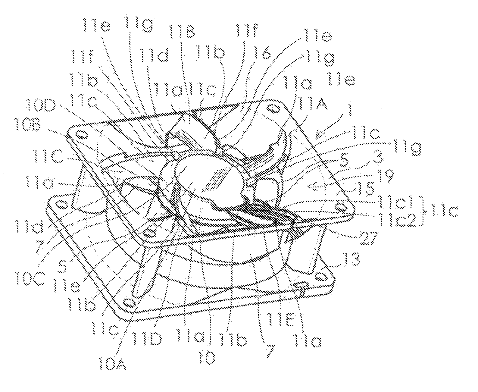
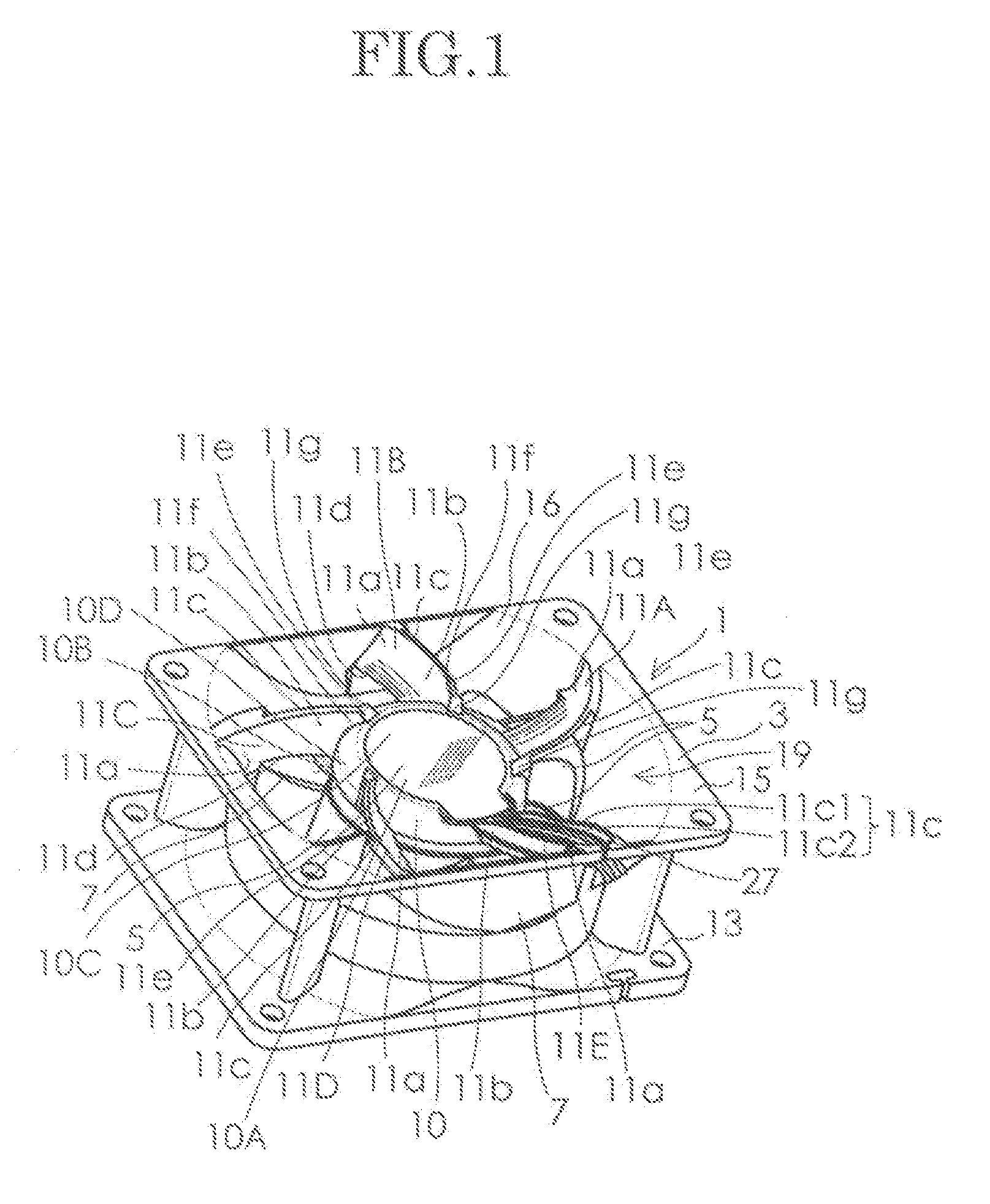
[0033] An embodiment of an axial-flow fan according to the present invention will be hereinafter described in detail with reference to the accompanying drawings. FIG. 1 is a perspective view of an axial-flow fan 1 according to an embodiment of the present invention as viewed from the right upper front side thereof, where lead wires are omitted. FIG. 2 is a front view of the axial-flow fan 1 of the embodiment shown in FIG. 1, and FIG. 3 is a rear view thereof. FIG. 4 is a right-side view of the axial-flow fan 1 shown in FIG. 2. FIG. 5 is a cross-sectional view of the axial-flow fan 1 as taken along line 5-5 in FIG. 4 where an internal structure of a motor is omitted. FIG. 6 is a cross-sectional view of the axial-flow fan 1 as taken along line 6-6 in FIG. 4 where the internal structure of the motor is omitted. FIG. 7 is a cross-sectional view of the axial-flow fan as taken along line 7-7 in FIG. 2.

[0034] Referring to these figures, the axial-flow fan 1 comprises a fan housing 3 and a...


PUM


Abstract

An axial-flow fan according to the present disclosure can increase the amount of the airflow and simultaneously reduce the noise level. A plurality of stationary blades 11A to 11D are curved, in a convex manner, toward a rotating direction of an impeller. The plurality of stationary blades 11A to 11D are generally inclined so that discharge-side edge portions 11d thereof are located more forward than suction-side edge portions 11c thereof in the rotating direction. An inclination angle θ4 of each of the plurality of stationary blades 11A to 11D in the vicinity of the external end portion 11a is larger than the inclination angle θ3 in the vicinity of the internal end portion 11b. The inclination angle is gradually changed from the vicinity of the external end portion 11a toward the vicinity of the internal end portion 11b.

Description

FIELD OF THE INVENTION [0001] The present invention relates to an axial-flow fan used for cooling an electric component or the like. BACKGROUND OF THE INVENTION [0002]FIG. 16 is a perspective view of an axial-flow fan equipped with stationary blades shown in FIG. 1 of US Design Patent No. D506540 (Official Gazette) FIG. 17 is a rear view of a conventional axial-flow fan shown in FIG. 5 of the same Official Gazette. As shown in these figures, in conventional axial-flow fans equipped with stationary blades, each of a plurality of stationary blades 101 is curved, in a convex manner, toward one side in a circumferential direction of a shaft. The plurality of stationary blades 101 are generally inclined so that the suction-side edge portions 101 are located at an opposite side to the suction-side edge portions in the circumferential direction of the shaft. The plurality of stationary blades are inclined at a substantially constant angle. [0003] However, it is impossible for the conventio...

Claims


Application Information

Patent Timeline
IPC IPC(8): F01D9/00
CPCF04D25/0613F04D29/542H05K7/20172F04D29/661F04D25/0646F04D29/544
Inventor ISHIHARA, KATSUMICHIOOSAWA, HONAMIMIYAZAWA, MASASHIIKEDA, TOMOAKI
Owner SANYO DENKI CO LTD
Why Eureka
Try Eureka