Particulate filter

a technology of particle filter and filtration media, which is applied in the direction of machine/engine, separation process, other domestic articles, etc., can solve the problems of not revealing a filter and the structure of the filtration media of fanselow that does not lend itself to effective filtering of very small soot particles, etc., and achieve the effect of reducing the number of regulated chemical species

Inactive Publication Date: 2007-05-31
CATERPILLAR INC
View PDF3 Cites 9 Cited by
  • Summary
  • Abstract
  • Description
  • Claims
  • Application Information

AI Technical Summary

Benefits of technology

[0011] In another embodiment, a method of reducing regulated chemical species within an exhaust stream of an engine is provided. The method comprises the steps of providing a particulate filter, said filter comprising, at least one first piece, said first piece comprising non-linear channels and at least one second piece adjacent to the at least one first piece, catalyzing the particulate filter with a catalyst, passing exhaust stream through the filter, filtering at least some particulate matter from the exhaust stream, and chemically converting at least some NOx from the exhaust stream with the catalyst.

Problems solved by technology

Although Fanselow discloses a filtration media, generally, it does not disclose a filter that could effectively remove particulate matter and other combustion byproducts within the exhaust stream of an engine.
Further, the microscopic structure of the filtration media of Fanselow does not lend itself to effectively filter very small soot-sized particles that are often present in engine exhaust.

Method used


Image

  • Particulate filter
  • Particulate filter
  • Particulate filter

Examples


Embodiment Construction

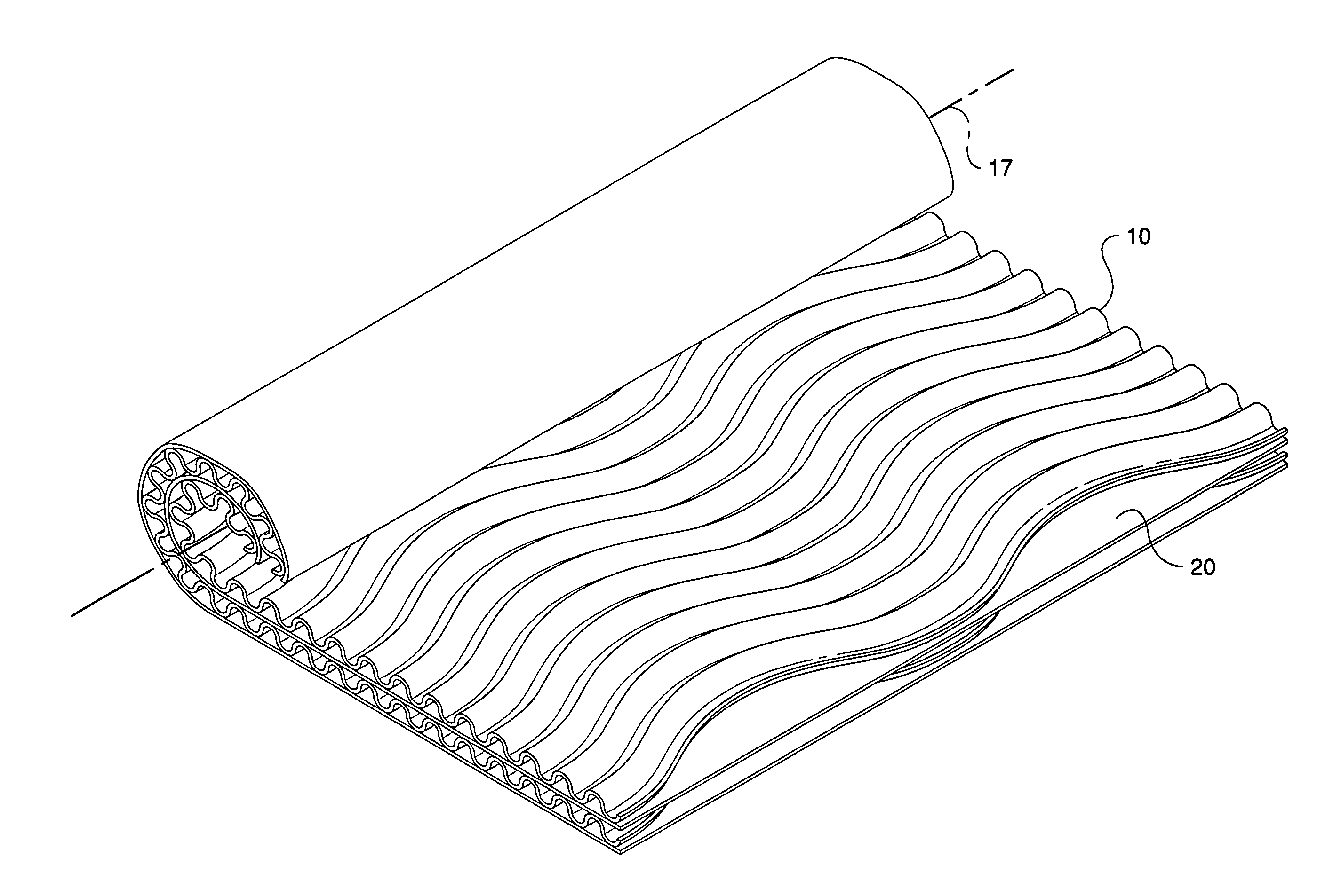
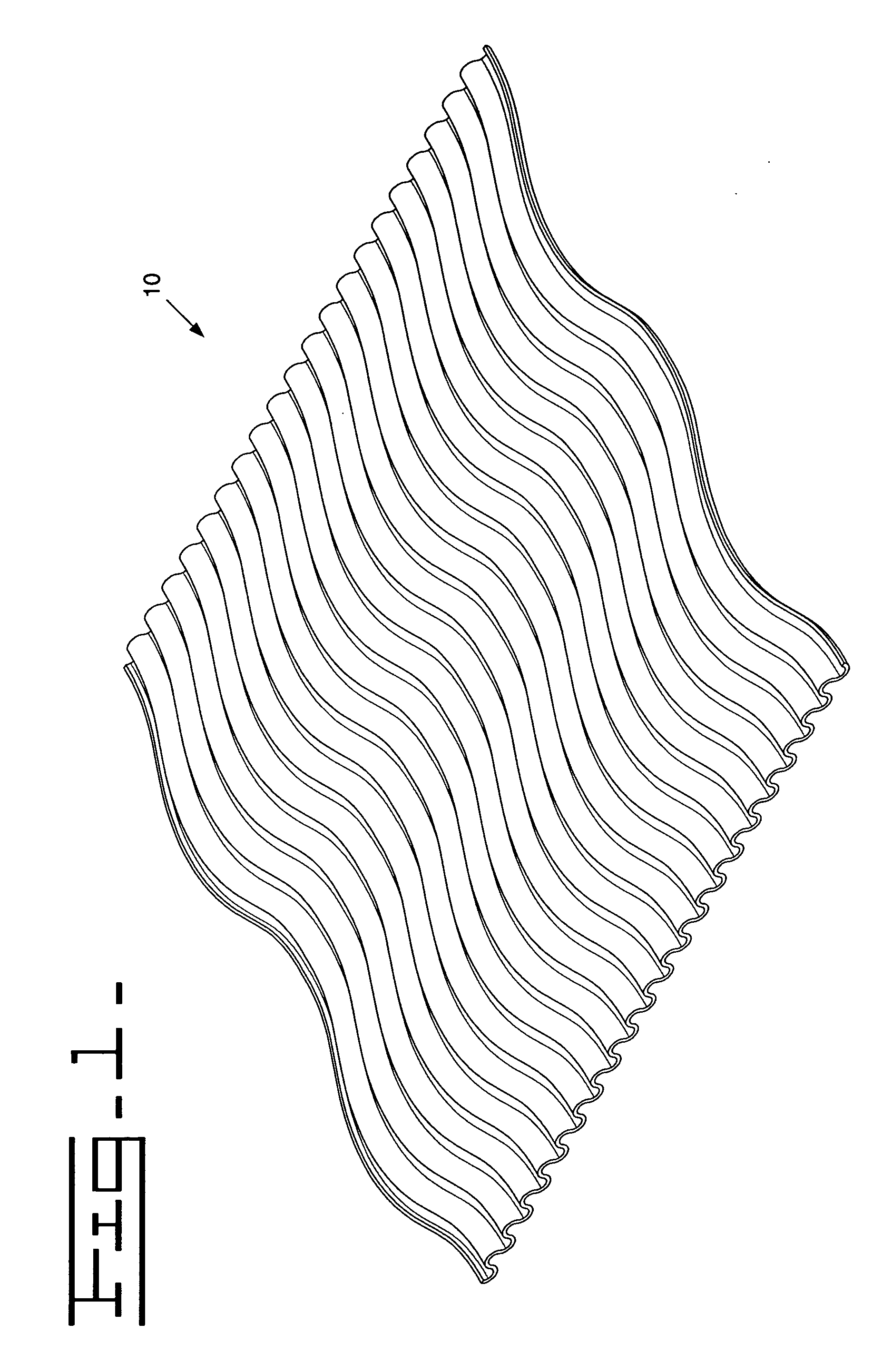
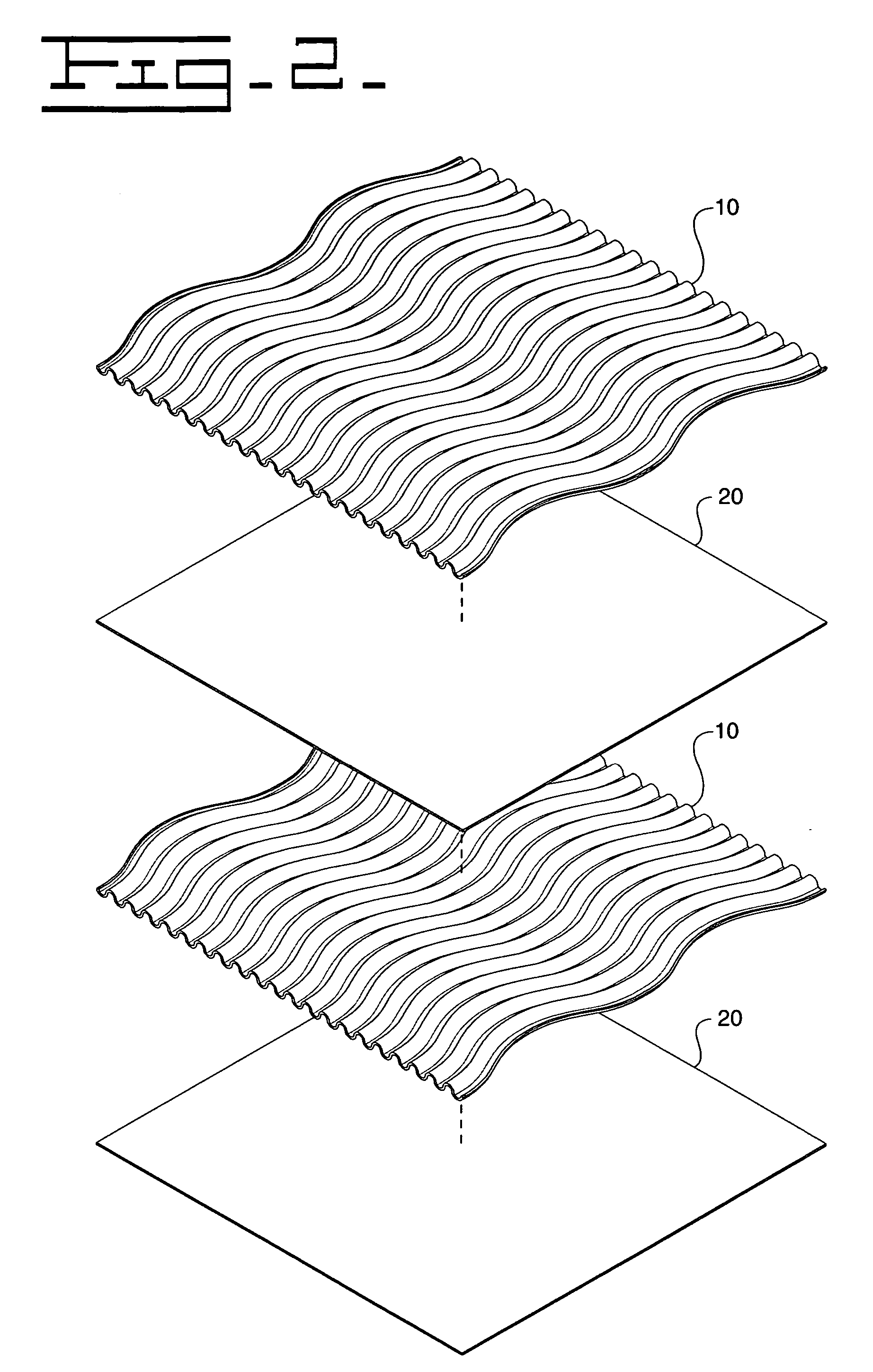
[0017]FIG. 1 is a perspective view of a filter piece 10 with non-linear channels 16. In this particular embodiment, channels 16 are sinusoidal in shape along the entire length of channels 16. Channels 16 are configured to receive fluid flow, such as exhaust gas fluid flow, when formed as part of a particulate filter 30 (shown in FIGS. 3 and 5). The non-linear nature of channels 16 promotes turbulent fluid flow, which may increase the efficiency of filtration as well as the chemical conversion by any chemical catalyst, if present.

[0018] Filter piece 10 may also be constructed of a porous material, which facilitates filtration of particulate matters. In particular, piece 10 comprises sintered metal fibers or porous metal-based foam, which provides for improved filtration efficiency. The porous nature of pieces 10 and or 20 permit the filtration of soot-sized particles of about 1 micrometer and larger.

[0019] Although the depicted channels 16 in FIGS. 1 and 2 are sinusoidal, the reade...


PUM

PropertyMeasurementUnit
diameteraaaaaaaaaa
diameteraaaaaaaaaa
diametersaaaaaaaaaa

Abstract

A particulate filter and a method for reducing pollutants are provided. The particulate filter comprises at least one first piece, said first piece comprising non-linear channels, and at least one second piece adjacent to the at least one first piece. The particulate filter is configured such that either the at least one first piece or the at least one second piece comprise either sintered metal fibers or porous metallic foam. The method comprises the steps of providing a particulate filter, said filter comprising, at least one first piece, said first piece comprising non-linear channels and at least one second piece adjacent to the at least one first piece, catalyzing the particulate filter with a catalyst, passing exhaust stream through the filter, filtering at least some soot from the exhaust stream, and chemically converting at least some NOx from the exhaust stream with the catalyst.

Description

[0001] This application is a continuation-in-part of application Ser. No. 11 / 289,213, filed Nov. 29, 2005, the contents of which are hereby incorporated by reference.U.S. GOVERNMENT RIGHTS [0002] This invention was made with government support under the terms of DE-FC26-02AL67974 awarded by the Department of Energy. The government may have certain rights in this invention.Technical Field [0003] The present disclosure relates to a particulate filter, an exhaust system of an internal combustion engine comprising a particulate filter, and a method for reducing regulated emissions from an internal combustion engine. More particularly, the present disclosure relates to a particulate filter that is configured to at least partially filter a portion of unwanted combustion byproducts that are emitted from the exhaust system of an internal or external combustion engine. BACKGROUND [0004] There are millions of engines in use throughout the world. Many of these engines are internal combustion e...

Claims


Application Information

Patent Timeline
Patent Type & Authority Applications(United States)
IPC IPC(8): B01D50/00B21D51/16B01D53/34
CPCF01N3/0222F01N3/2814F01N3/2821F01N2330/02Y10T29/49345F01N2330/42F01N2510/06Y02T10/20F01N2330/38Y02T10/12
Inventor DACOSTA, HERBERT F.HABEGER, CRAIG F.POLLARD, MICHAEL J.
Owner CATERPILLAR INC
Why Eureka
Try Eureka