Folding electric apparatus

a technology of electric apparatus and folding rod, which is applied in the direction of flexible/turnable line connectors, separation processes, flexible/turnable connectors, etc., can solve the problems of difficult to maintain the accuracy of a rotary shaft to be high, complicated assembling work, and insufficient rigidity of hinges, etc., to achieve easy incorporation and lay, and maintain the effect of rigidity of hinges

Inactive Publication Date: 2007-05-31
FUJITSU LTD
View PDF4 Cites 17 Cited by
  • Summary
  • Abstract
  • Description
  • Claims
  • Application Information

AI Technical Summary

Benefits of technology

[0021] Due to the above structure, the rigidity of the hinge can be maintained sufficiently high, and the signal wires for connecting the first housing with the second housing can be easily incorporated and laid.

Problems solved by technology

Therefore, the following problems may be encountered in the conventional folding electronic apparatus.
Therefore, the rigidity of the hinge is not sufficiently high compared with the rigidity of the structural members of the chassis.
Accordingly, it is difficult to maintain the accuracy of a rotary shaft to be high.
In the conventional folding electronic apparatus, when the movable portion and the stationary portion are connected to each other by the signal wires at the time of assembling, the assembling work is complicated.
Therefore, the rigidity of the hinge is not sufficiently high.
Accordingly, it is difficult to maintain the accuracy of the rotary shaft to be sufficiently high.
Further, there is a possibility that the hinge is independently deformed when a shock is given to the apparatus.
Furthermore, in the conventional folding electronic apparatus, it is difficult to incorporate the signal wires extending between the movable portion and the stationary portion.

Method used


Image

  • Folding electric apparatus
  • Folding electric apparatus
  • Folding electric apparatus

Examples


Embodiment Construction

[0030] Referring to the accompanying drawings, an embodiment of the present invention will be explained in detail below.

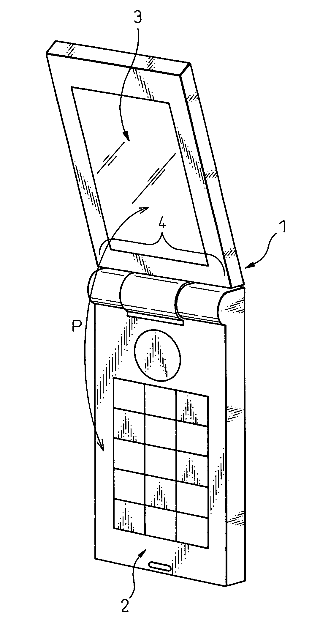
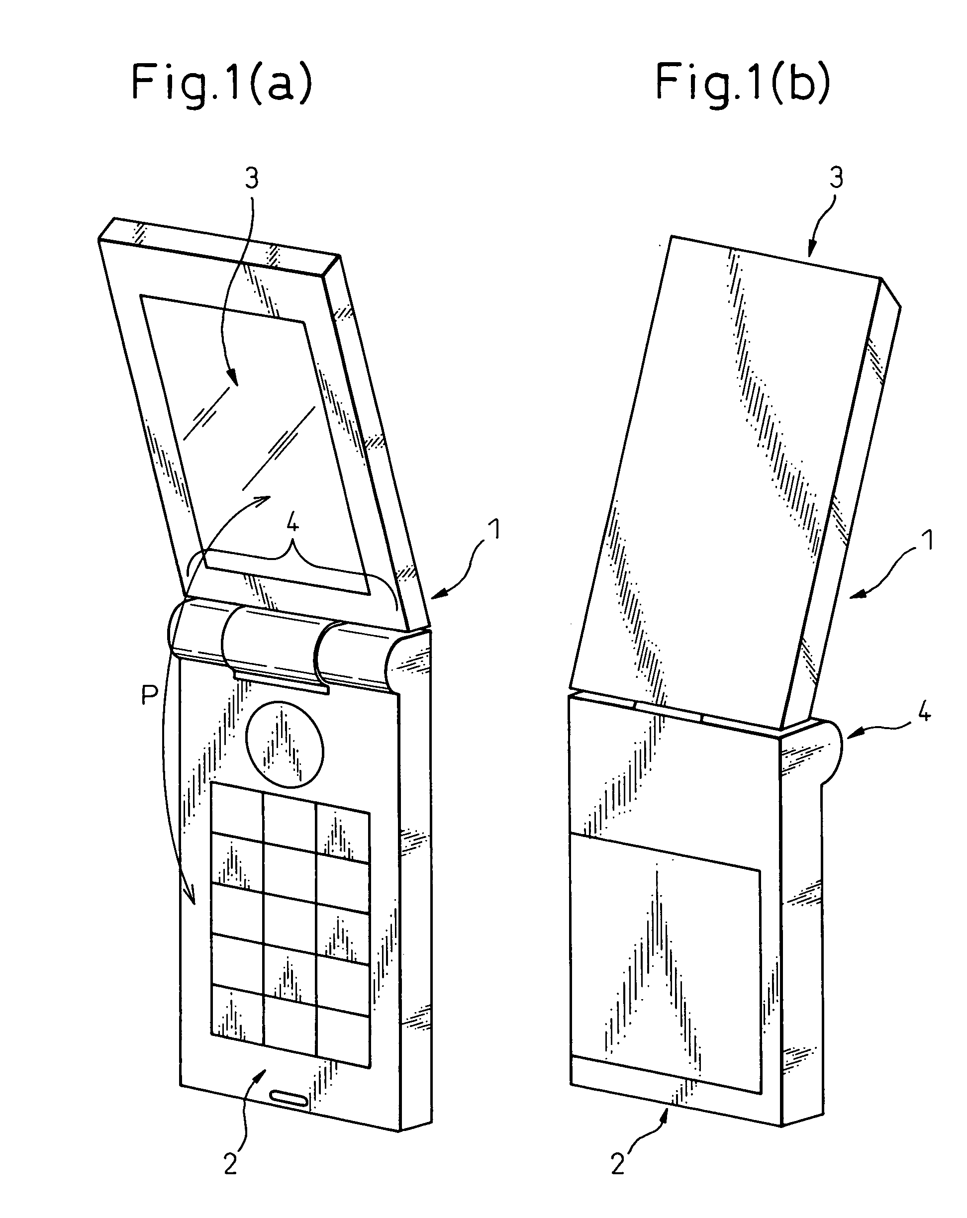
[0031] FIGS. 1(a) and 1(b) are views showing a folding mobile phone to which the present invention can be applied. FIG. 1(a) is a perspective view showing a folding mobile phone of the present invention in an open state, wherein the view is taken from the liquid crystal display face side. FIG. 1(b) is a perspective view showing a folding mobile phone of the present invention in an open state, wherein the view is taken from the reverse face side.

[0032] The folding mobile phone 1 is composed as follows. The first housing (the stationary portion) 2, in which the input operating portion such as various keys and buttons and the telephone microphone are provided, and the second housing (the movable portion) 3, in which the liquid crystal display portion and the telephone ear phone are provided, are connected to each other by the hinge 4 so that the first housing 2 and ...


PUM

PropertyMeasurementUnit
angleaaaaaaaaaa
angleaaaaaaaaaa
flexibleaaaaaaaaaa

Abstract

A folding electronic apparatus is proposed, the rigidity of the hinge of which is sufficiently high, in which signal wires for connecting a movable portion with a stationary portion can be easily incorporated. The apparatus includes: a stationary portion (2) and a movable portion (3) which are connected to each other by a hinge (4), capable of being opened and closed, the hinge includes: a pipe portion (32) having a first slit (35) on a side wall, the pipe portion being attached to one of the movable portion and the stationary portion; and a hollow shaft (24) having a second slit (25) on the side wall, the hollow shaft (24) being attached to the other of the movable portion and the stationary portion, the hollow shaft (24) being engaged inside the pipe portion, wherein the first and second slits extend to positions shifted from an engaging portion of the pipe portion with the hollow portion in the axial direction and define opening portions (25a, 35a) of the first and second slits.

Description

BACKGROUND OF THE INVENTION [0001] 1. Field of the Invention [0002] The present invention relates to a folding electric apparatus. More particularly, the present invention relates to a folding electric apparatus having a hinge (an opening and closing mechanism). The present invention can be applied to various folding electronic apparatus having a hinge, such as a stationary communication terminal and a portable electronic apparatus, for example, a mobile phone, a portable communication terminal, a portable electronic note, a portable electronic book, a portable electronic dictionary and so forth. [0003] The folding electronic apparatus includes: a first housing, for example, a stationary portion, in which an operation portion is mainly provided; and a second housing, a movable portion, in which a display portion such as a liquid crystal display is mainly provided, wherein the first housing and the second housing are connected with each other by a hinge, and the movable portion can b...

Claims


Application Information

Patent Timeline
Patent Type & Authority Applications(United States)
IPC IPC(8): H01R39/00H04M1/02H04M1/12
CPCH01R35/02H04M1/0216H01R2201/16B01D35/16B01D37/04B01D2201/16
Inventor SHINODA, TAKAO
Owner FUJITSU LTD
Why Eureka
Try Eureka