
Self-cooled photo-voltaic device and method for intensification of cooling thereof

a self-cooled, photo-voltaic technology, applied in the direction of photo-voltaics, semiconductor devices, electrical equipment, etc., can solve the problems of increased manufacturing costs, increased manufacturing costs, and large dimensions, and achieves cost-effectiveness, easy manufacturing and incorporation, and enhanced outward ir radiation intensity

Inactive Publication Date: 2006-07-27
GILMAN BORIS
View PDF7 Cites 18 Cited by
  • Summary
  • Abstract
  • Description
  • Claims
  • Application Information

AI Technical Summary

Benefits of technology

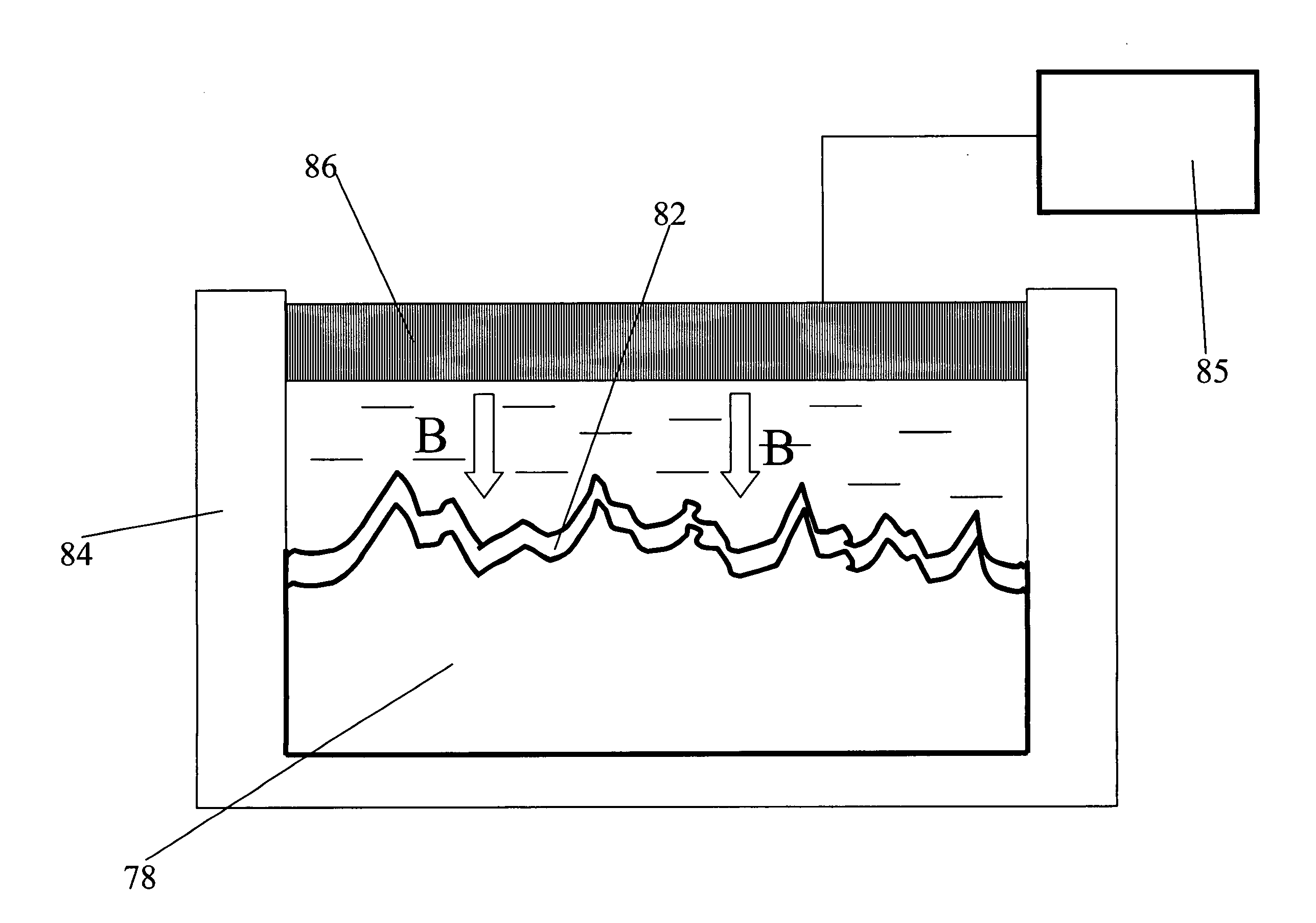
"The present invention provides a method and means for radiative cooling of PV devices, such as solar cells and solar modules, by emitting IR radiation outward. The cooling unit consists of a PV unit and a light-transparent radiative cooling unit that covers the light-receiving surface of the PV unit and has an electric charge positively induced in it for re-arranging the spectrum of the IR radiation towards the spectral range of the ATW. The cooling unit is easy to fabricate, compatible with current PV device designs, and cost-effective. The invention also provides a self-cooled PV device with a quantum-assisted radiative cooling unit that operates on the principle of quantum-electrical control of IR radiation intensity. The use of IR emitting layers in combination with a textured surface of the PV unit significantly enhances the outward IR radiation intensity and increases the heat removal rate, resulting in improved cooling efficiency of the PV device as a whole."

Problems solved by technology

It is clear, however, that operating at elevated temperatures has a significant negative impact on the solar energy production.
Furthermore, heating of the cell is limited and the fluid leaving the radiator is heated by the beam striking the cell.
While TPV systems are well known and have some specific applications, they have larger dimensions, greater complexity, and higher manufacturing costs, and therefore can not be considered an efficient tools for cooling conventional SC's and SM's.
However, none of the above references either relates specifically to a PV device or describe the possibility of intensification of cooling due to interaction between the surface emitting layers (coatings) and the underlying textured surface of SC or SM.
A disadvantage of this system is that it requires the use of an additional energy source for driving the cooling liquid.
Provision of a cooling-liquid supply system makes the construction more complicated and expensive.

Method used


Image

  • Self-cooled photo-voltaic device and method for intensification of cooling thereof
  • Self-cooled photo-voltaic device and method for intensification of cooling thereof
  • Self-cooled photo-voltaic device and method for intensification of cooling thereof

Examples


Embodiment Construction

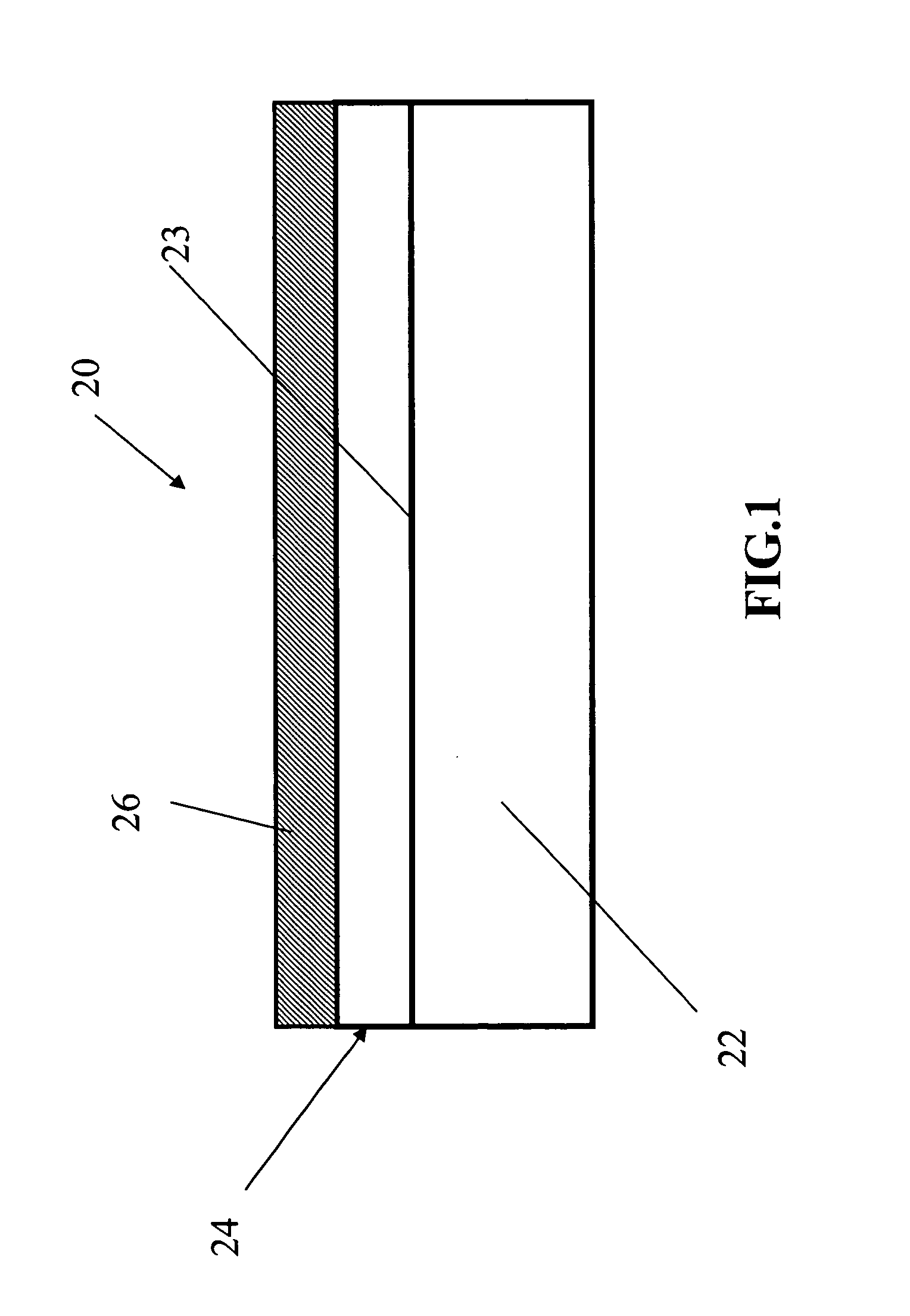
[0027] In a simplified general form, a PV device 20 of the invention is shown in FIG. 1, which is a sectional view of the device. It can be seen that the PV device 20 contains a conventional PV unit 22 that may comprise, e.g., a Si-solar cell of the type produced by e.g. BP Solar Co., or described, e.g., by M. A. Green in >, 74, 2003, pp. 181-192. The structure of such a solar cell is well known and is beyond the scope of the present invention. If necessary, the PV unit 22 may be represented by a solar module of the type produced, e.g., by BP Solar Co. It is understood that the above references are given only as examples and do not limit the scope of the application of the invention, provided that a solar-energy generation unit is of a PV type.

[0028] The light-receiving side 23 (FIG. 1) of the PV unit 22 supports a cooling-enhancing unit 24 in the form of an IR-emitting layer or layers, which are described in detail later. A characteristic feature of the cooling-enhancing unit 24 i...


PUM


Abstract

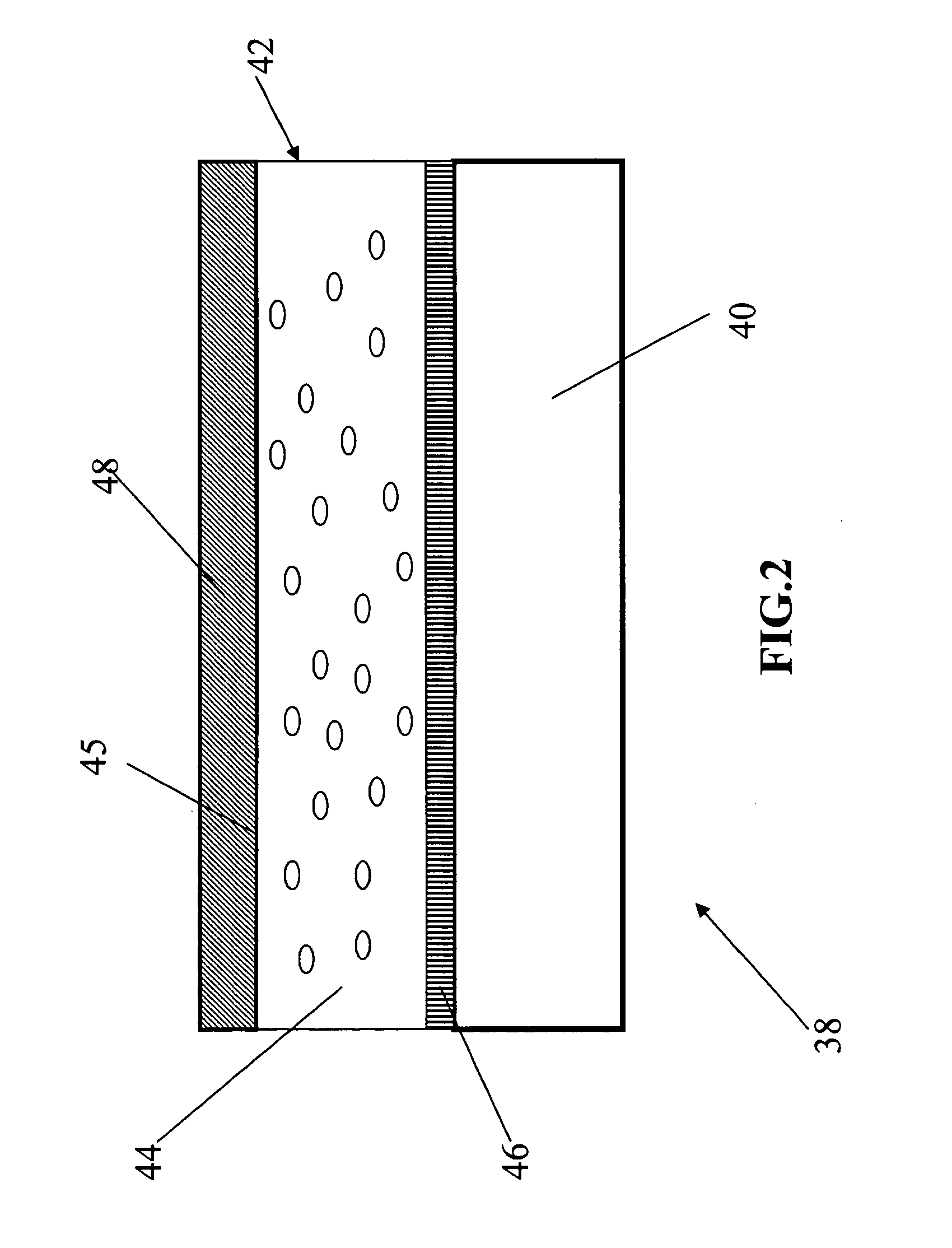
The invention provides a self-cooled PV device that consists of a PV unit and a radiative cooling unit with specific cooling-enhancing means that covers the solar-energy absorbing side of the PV unit. The aforementioned specific radiation enhancing means may have an electric charge positively induced in the radiative cooling unit for re-arranging the spectrum of the IR radiation towards the spectral range of the ATW. The radiation enhancing means may be comprised of a pre-charged texture formed on the light-receiving surface of the PV unit and coated with an anti-reflection film, a sealed chamber filled with a dipole gas or a mixture of gases, or a combination of the pre-charged texture and the aforementioned gas-filled chamber.

Description

CROSS-REFERENCES TO RELATED APPLICATIONS [0001] Not Applicable BACKGROUND OF THE INVENTION [0002] 1. Field of the Invention [0003] The present invention relates to the field of solar-energy conversion, in particular, to self-cooled photo-voltaic devices such as solar cells, solar modules, and solar panels. More specifically, the invention relates to photo-voltaic devices combined with means for intense cooling of such devices by removing heat generated by such devices in the course of their operation. The invention also relates to a method of intensification of cooling of the aforementioned devices. BACKGROUND OF THE INVENTION [0004] 2. Description of Related Art [0005] A photovoltaic (hereinafter referred to as <<PV>>) cell comprises P-type and N-type semiconductors with different electrical properties, joined together. The joint between these two semiconductors is called the “P-N junction.” Sunlight striking the PV cell is absorbed by the cell. The energy of the absorb...

Claims


Application Information

Patent Timeline
Patent Type & Authority Applications(United States)
IPC IPC(8): H01L31/042
CPCH01L31/0236H01L31/052Y02E10/52H01L31/02363Y02E10/50
Inventor GILMAN, BORIS
Owner GILMAN BORIS
Learn More