
Proposed running track design for fairer 200 m and 400 m races

a running track and race technology, applied in the field of race course design, can solve the problems of less thrust force available for increasing or maintaining speed, serious lack of parity between competitors in track events, and lack of parity, so as to eliminate the disproportionate effect of centrifugal for

Inactive Publication Date: 2007-05-31
ALPHADEV
View PDF14 Cites 8 Cited by
  • Summary
  • Abstract
  • Description
  • Claims
  • Application Information

AI Technical Summary

Benefits of technology

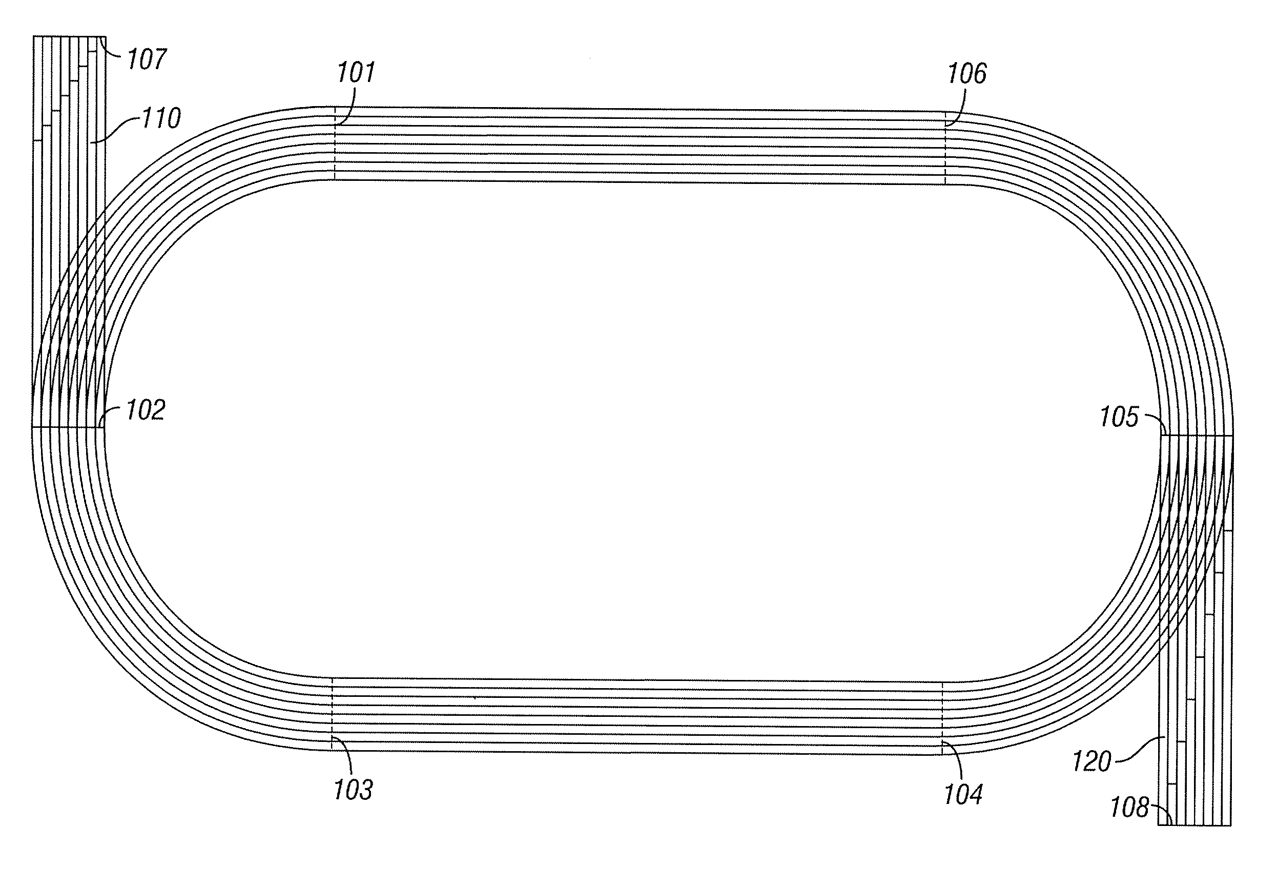
[0006] The present invention is directed to a system and method for conducting a more fair race around an oval track by configuring the track such that the runner in each lane runs an arc angle equal to the runners in other lanes. Such a configuration eliminates the disproportionate effect of centrifugal force on competitors running in inner lanes. Embodiments of the invention provide for the addition of a straight section to a standard oval track extending from the midpoint of a curved section and perpendicular to the existing straightaway section. Runners in each lane start at staggered locations on the straight section and proceed through a curved quadrant and to a finish line on the straightaway furthest away from the straight section. The staggered starting locations are chosen such that the runner in each lane travels an equal distance from the starting location to a common finish line on the straightaway. The straight section may have a rectangular shape in some embodiments or may be angled to accommodate the staggered starting positions such that the straight section extends further at lane 1 than at the outer lane.

Problems solved by technology

Despite this “staggered start” positioning that equalizes the distance run by each competitor, a serious lack of parity between competitors in track events remains.
This lack of parity stems from the “centrifugal effect.” An athlete running a curve must expend some of his or her thrust force to combat the centrifugal force, leaving less thrust force available for increasing or maintaining speed.
Such a 100 m extension may prove problematic within a track venue as it may not fit within the playing surface and may result in inferior sightlines for spectators.

Method used


Image

  • Proposed running track design for fairer 200 m and 400 m races
  • Proposed running track design for fairer 200 m and 400 m races
  • Proposed running track design for fairer 200 m and 400 m races

Examples


Embodiment Construction

Three-parameter Model

[0017] The inherent discrepancy that results due to lane assignment may also be observed though the use of a three-parameter model of sprinting. This model may be used to simulate 200 m runs in different lanes. Changing one parameter value (constant but not maximal thrust force) allows simulation of 400 m runs in different lanes. This model derives from earlier models proposed in Joseph B. Keller, “A Theory of Competitive Running,” Physics Today 26(9) pp. 42-47 (1973) (“Keller), and in Igor Alexandrov and Philip Lucht, “Physics of Sprinting,” American Journal of Physics 49 pp. 254-257 (1981) (“Alexandrov and Lucht”), each of which is hereby incorporated by reference in its entirety. One of the parameters is the maximum thrust force that a runner can exert; this parameter also appears in Keller and Alexandrov and Lucht. The second parameter characterizes the resistive force on a runner, which is assumed to be proportional to the square of the speed; the assumpti...


PUM


Abstract

The present invention is directed to a system and method for conducting a more fair race around an oval track by having runners in each lane run equal arc angles. Such a configuration eliminates the disproportionate effect of centrifugal force on competitors running in different lanes. Embodiments of the invention provide for the addition of a straight section to a standard oval track extending from a curved section perpendicular to the existing straightaway section. Runners in each lane start at staggered locations on the straight section. The staggered starting locations are chosen such that each runner travels an equal distance from the starting location to a common finish line. A single straight section may be employed to conduct races covering the entire length and half the length of the oval track or two straight sections may be employed to allow finishes for both races at a common finish line.

Description

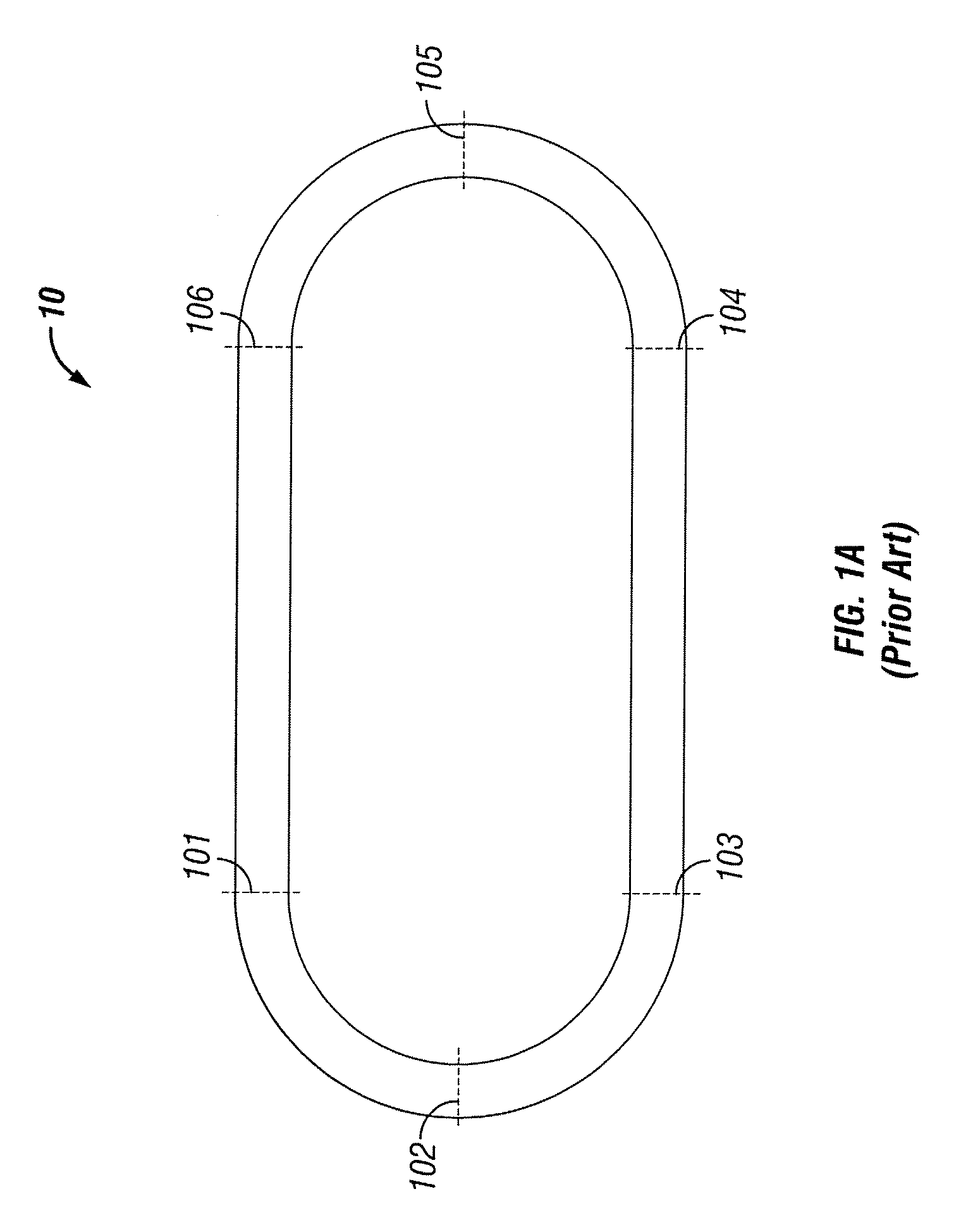
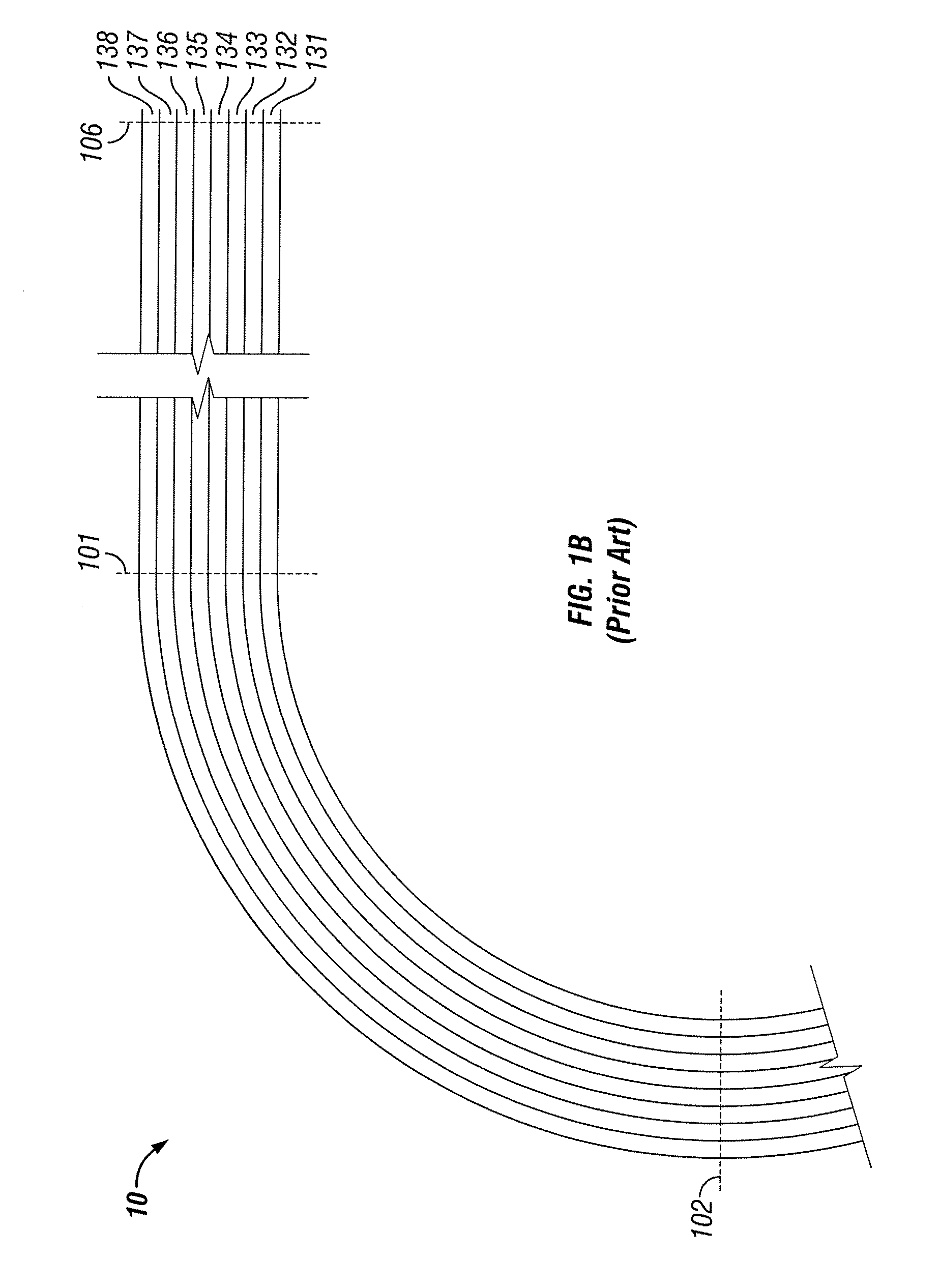
CROSS-REFERENCE TO RELATED APPLICATIONS [0001] The present application claims priority to U.S. Provisional Application Ser. No. 60 / 740,263, filed Nov. 29, 2005, the entirety of which is hereby incorporated by reference.TECHNICAL FIELD [0002] The present invention relates to the field of race course design.BACKGROUND OF THE INVENTION [0003] Several sporting events involve competitors racing around an oval track consisting of two straightaway portions and two curved portions connecting the straightaway portions. FIG. 1A illustrates a traditional track 10 with straightaway portions extending from point 101 to 106 and point 103 to 104 and curved portions extending from point 101 to 102 to 103 and point 104 to 105 to 106. A traditional track 10 often includes several parallel lanes where lane 1 is the innermost lane. FIG. 1B shows a portion of track 10 extending from point 106 to 101 to 102. As can be seen in FIG. 1B, track 10 includes of 8 parallel lanes 131-138. In several events utili...

Claims


Application Information

Patent Timeline
Patent Type & Authority Applications(United States)
IPC IPC(8): A63K1/00
CPCA63K1/00
Inventor CARROLL, MICHAEL M.
Owner ALPHADEV
Learn More