Vehicle drive control system and method

a control system and vehicle technology, applied in the direction of braking systems, instruments, analogue processes for specific applications, etc., can solve the problems of insufficient control of the brake assist control, the difficulty of the driver turning the vehicle as intended, and the inability of the driver to turn the vehicle as intended by the driver's steering operation, etc., to achieve the effect of reducing torsional stress, increasing torsional stress, and increasing the likelihood of an emergency operation by the driver

Inactive Publication Date: 2007-05-31
TOYOTA JIDOSHA KK
View PDF4 Cites 12 Cited by
  • Summary
  • Abstract
  • Description
  • Claims
  • Application Information

AI Technical Summary

Benefits of technology

[0010] According to this structure, a determination is made whether hard braking is being applied by, for example, a driver of the vehicle, and if so, a determination is then made whether emergency steering operation is likely to be performed by, for example, the driver. If it is determined that an emergency steering operation is likely to be performed, the steering characteristic control mechanism is controlled to vary the steering characteristic of the vehicle to increase oversteering component of the vehicle so that it becomes greater than it is when the likelihood of an emergency steering operation is low, whereby the driver can turn the vehicle easily during the hard braking. As such, for example, when the driver performs an emergency steering operation during bard braking, the vehicle can be turned as much as the driver intends while being braked as required.
[0013] The roll stiffness allocation control mechanism may include a front stabilizer that applies a torsional stress to the front wheels and is capable of changing the magnitude of the torsional stress to the front wheels and a rear stabilizer that applies a torsional stress to the rear wheels and is capable of changing the magnitude of the torsional stress to the rear wheels. The control portion may bias the roll stiffness allocation towards the rear wheels by reducing the torsional stress to the front wheels through control of the front stabilizer.
[0016] According to this structure, compared to the case where the damping coefficient for the outside front wheel is not reduced, the vehicle height at the outside front wheel is lowered, and therefore the difference in height between the roll center at the front wheels and the center of gravity of the vehicle increases. Thus, if the vehicle is turned in this state, a larger roll moment occurs at the front wheels, which increases the vertical load of the outside front wheel and reduces the vertical load of the inside front wheel, thus enabling a larger amount of lateral force to be produced at the outside front wheel. The larger roll moment at the front wheels also reduces the braking force on the inside front wheel and thus causes a difference in braking force between the left and right front wheels, which causes a yawing moment to occur in the direction to assist the vehicle to turn. Thus, the driver can steer the vehicle more easily during turning of the vehicle, especially in the initial stage of the steering operation.
[0017] In another form of the invention, the main control portion may be configured to control the steering characteristic control mechanism so as to increase the amount by which the steering characteristic of the vehicle is varied to increase oversteering component of the vehicle as the likelihood of an emergency steering operation increases.
[0020] In another form of the invention, the main control portion may be configured to control the roll stiffness allocation control mechanism so as to increase the amount by which the roll stiffness allocation between the front wheels and the rear wheels is biased towards the rear wheels as the likelihood of an emergency operation by a driver increases.
[0021] In another form of the invention, the main control portion may be configured to bias the roll allocation between the front wheels and the rear wheels towards the rear wheels by reducing the torsional stress applied from the front stabilizer to the front wheels and increasing the torsional stress applied from the rear stabilizer to the rear wheels.

Problems solved by technology

When very large braking forces are being applied to the wheels, such as during the brake assist control, the forces produced at the wheels, particularly at the front wheels, are mainly used to brake the vehicle, and therefore the amount of lateral force that can be produced at the front wheels is relatively small, which makes it difficult for the driver to turn the vehicle as he or she intends.
However, the difficulty in turning the vehicle as intended by the driver's steering operation under the brake assist control has not been addressed in the conventional drive control systems.

Method used


Image

  • Vehicle drive control system and method
  • Vehicle drive control system and method
  • Vehicle drive control system and method

Examples


first embodiment

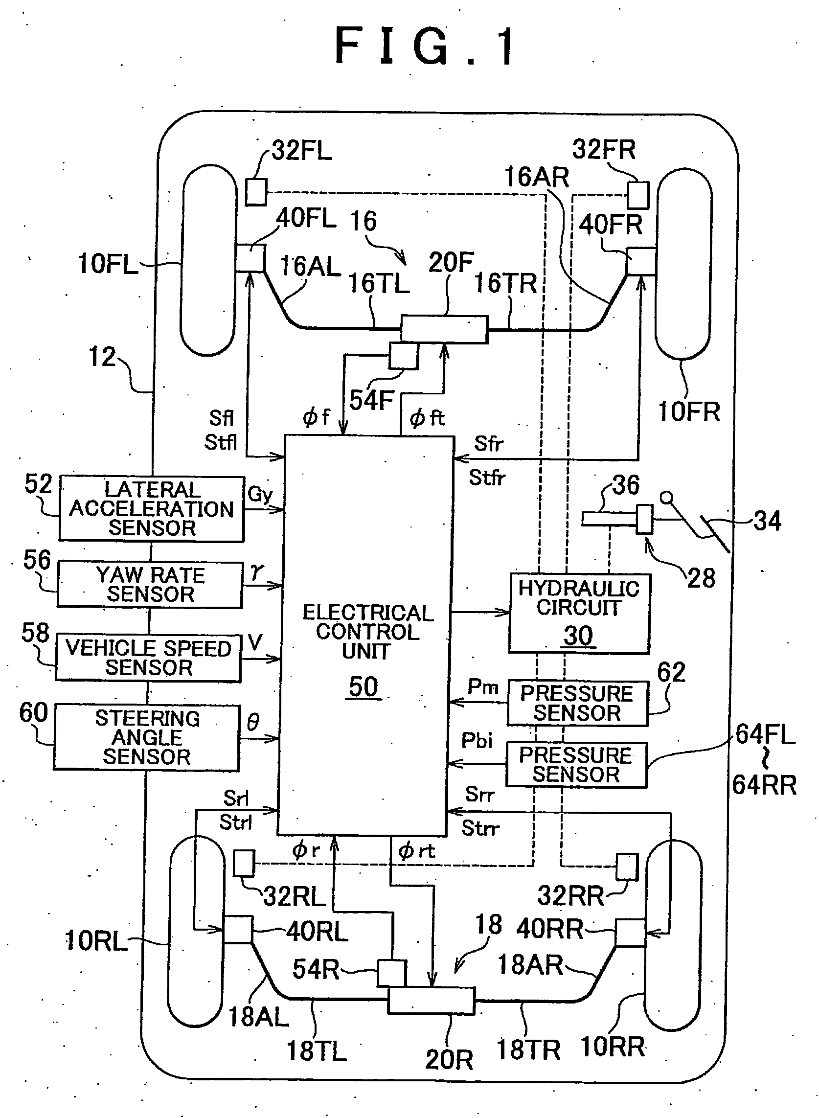
[0040]FIG. 1 is a schematic diagram of a vehicle drive control system according to the invention, which is applied to a vehicle having front and rear active stabilizers.

[0041] In FIG. 1, reference numerals 10FL and 10FR denote left and right front wheels of a vehicle 12 as driven wheels, respectively, and reference numerals 10RL and 10RR denote left and right rear wheels of the vehicle 12 as drive wheels, respectively. The left and right front wheels 10FL and 10FR, which are also steered wheels, are steered via tie rods by a power steering apparatus (not shown) that is driven in response to a steering wheel (not shown) being operated by the driver.

[0042] An active stabilizer 16 is provided between the left and right front wheels 10FL and 10FR. An active stabilizer 18 is provided between the left and right rear wheels 10RL and 10RR. The active stabilizer 16 has a pair of torsion bars 16TL and 16TR, which extend coaxially to each other with the axis extending in the lateral direction...

second embodiment

[0086]FIG. 9 is a schematic diagram of a vehicle drive control according to the invention. In FIG. 9, components corresponding to those in FIG. 1 are denoted by the same reference numerals and symbols as in FIG. 1.

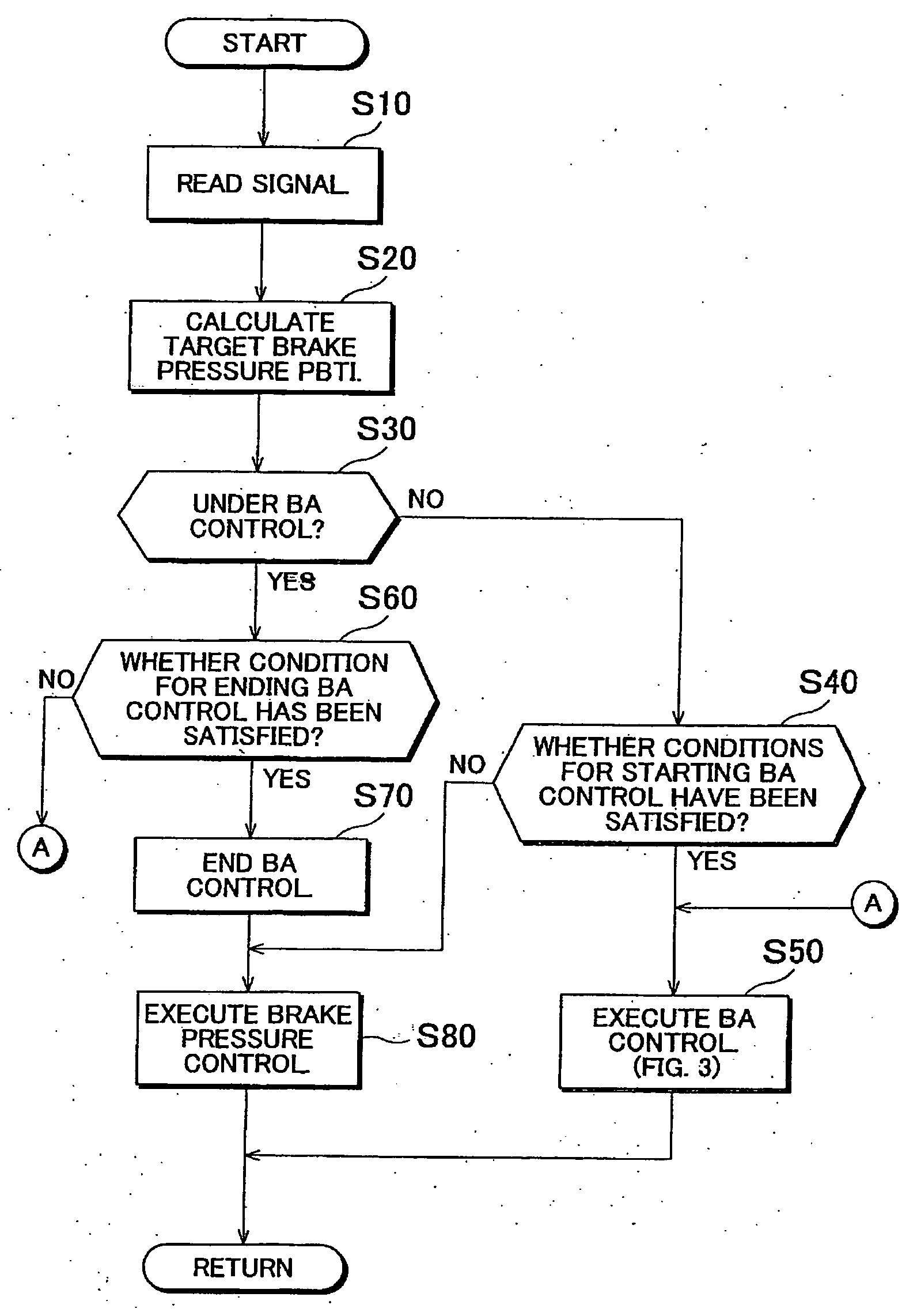
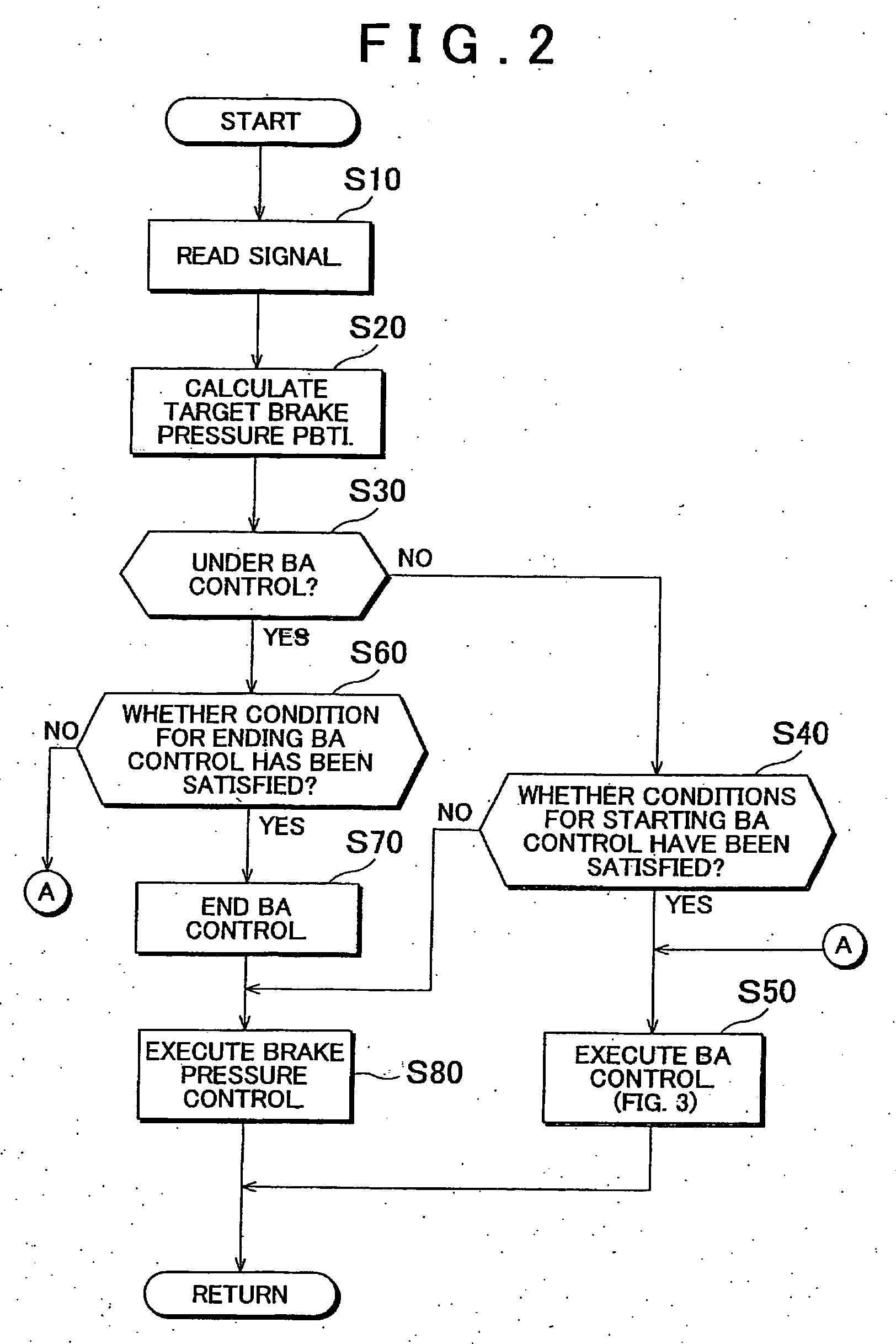
[0087] According to the second embodiment, a radar 66 is provided for detecting an obstacle in front of the vehicle and a distance L between the vehicle and the obstacle. A signal indicative of the distance L is inputted to the ECU 50. Based on the presence or absence of an obstacle and the distance L, the ECU 50 determines whether the driver is likely to perform emergency steering operation, and calculates a potential time Tc until the vehicle collides with the obstacle. The time Tc is obtained from the following equitation 1 representing the relationship between distance L, vehicle speed V, vehicle deceleration Gxb, and time Tc. The ECU 50 calculates a correction coefficient Ka such that the shorter the time Tc, the larger the coefficient Ka. Then, an index value Ks, whi...


PUM


Abstract

A drive control system for a vehicle includes a braking force control mechanism that controls braking forces on the wheels of the vehicle according to a braking operation, a steering characteristic control mechanism that varies the steering characteristic of the vehicle, a determination portion that determines whether an emergency steering operation is likely to de performed when hard braking is being applied, and a main control portion that controls the steering characteristic control mechanism so as to vary the steering characteristic of the vehicle to increase oversteering component of the vehicle if the determination portion determines that an emergency steering operation is likely to be performed.

Description

INCORPORATION BY REFERENCE [0001] The disclosure of Japanese Patent Application No. 2005-342328 filed on Nov. 28, 2005 including the specification, drawings and abstract is incorporated herein by reference in its entirety. BACKGROUND OF THE INVENTION [0002] 1. Field of the Invention [0003] The invention relates to a vehicle drive control system and method, and more particularly, to a vehicle drive control system and method for controlling the steering characteristic of the vehicle when hard braking is being applied by the driver. [0004] 2. Description of the Related Art [0005] One of the conventional vehicle drive control systems for vehicles such as automobiles is disclosed in JP-A-9-263233. This vehicle drive control system performs brake assist control in which additional brake pressures are produced when the driver is applying hard braking, so that the ratio of the braking force to the amount of the braking operation by the driver increases. [0006] When very large braking forces...

Claims


Application Information

Patent Timeline
Patent Type & Authority Applications(United States)
IPC IPC(8): G06G7/76B60G17/015B60G17/016B60G21/055B60T8/00
CPCB60G17/0162B60G17/0195B60G21/0555B60G2800/24B60G2800/9122B60G2800/92B60G2800/96B60T8/1755B60T8/3275B60T2201/03B60T2260/02B60W30/085
Inventor FUJITA, YOSHITAKA
Owner TOYOTA JIDOSHA KK
Why Eureka
Try Eureka