
Motion detection system and motion detection method

a technology of motion detection and motion detection method, which is applied in the field of touch panel, can solve the problems of unsatisfactory accuracy, high correlation between individuals, and significant interference of effective capacitance values (or capacitive effects), and achieve the effect of avoiding malfunction or mis-trigger, reducing noise, and increasing overall noise resistan

Inactive Publication Date: 2007-05-31
SUNPLUS TECH CO LTD
View PDF4 Cites 10 Cited by
  • Summary
  • Abstract
  • Description
  • Claims
  • Application Information

AI Technical Summary

Benefits of technology

"The invention is a motion detection system that uses a touch panel with metal sensors as detecting sensors. The system includes a control unit that generates a reference voltage and a control signal to connect the detecting sensors to a first or second voltage during a detecting stage. The detecting sensors are floated while the other sensors are connected to the first or second voltage, depending on the control signal. The detection unit calculates the discharge time of the detecting sensor and generates a detection result signal based on the voltage, the predetermined reference voltage, and a predetermined reference voltage. The control unit generates the motion signal based on the detection result signal. The invention uses the capacitive effect to detect the movement of a human's finger on the touch panel, and compensates for external environmental factors to avoid malfunction or mis-trigger. The invention has high noise-resistance and dynamic adjustment of reference values to compensate for changes in capacitance values."

Problems solved by technology

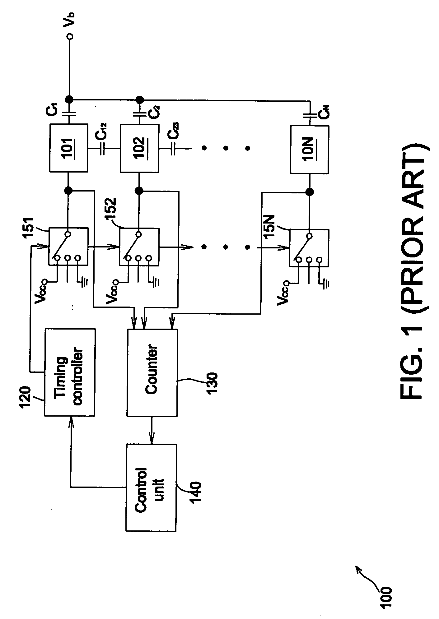
Even though the human's body does not contact the touch panel, some parasitic capacitance is still generated inside the touch panel circuit.
However, with respect to the conventional motion detection technique, the effective capacitance values (or capacitive effect) are significantly interfered by either external noises or external environmental factors while detecting.
Meanwhile, due to the different effective capacitance value for each individual and incapable of making real-time dynamic calibration, the traditional motion detection technique causes the problems of unsatisfactory accuracy and high correlation between individuals.

Method used


Image

  • Motion detection system and motion detection method
  • Motion detection system and motion detection method
  • Motion detection system and motion detection method

Examples


Embodiment Construction

[0022] The system and method for motion detection of the invention will be described with reference to the accompanying drawings.

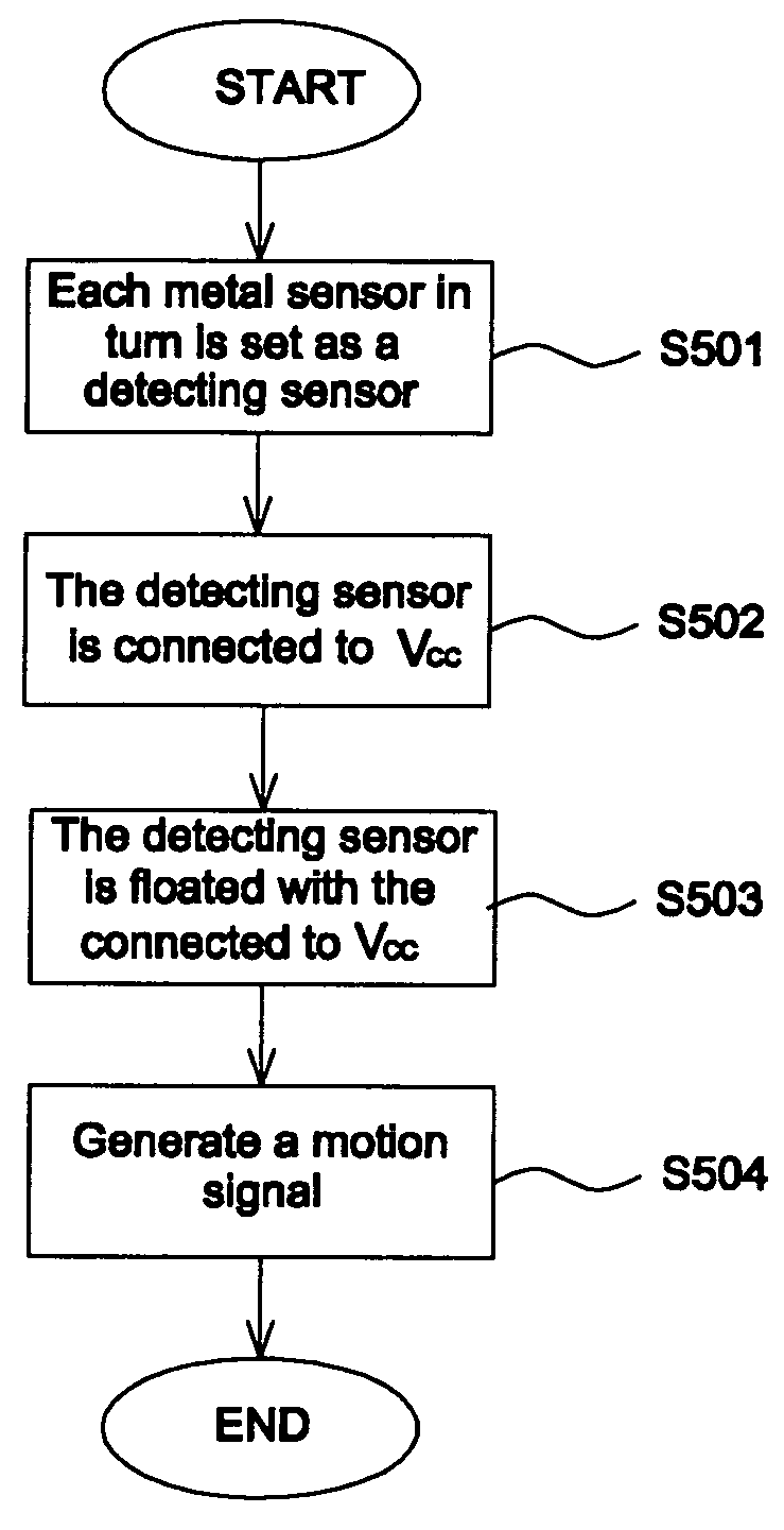
[0023]FIG. 3A shows a schematic block diagram illustrating a motion detection system according to the invention. Referring to FIG. 3A, the motion detection system 300 according to the invention comprises a touch panel 310, a plurality of switching units 151˜15N (N□2 and N is a positive integer), a detection unit 330, and a control unit 340. The touch panel 310 comprises a plurality of metal sensors 301˜30N, each of which in turn is set as a detecting sensor while in operation. Each of the switching units 15n (1 □n □N and n is a positive integer) is electrically connected to a corresponding metal sensor and then the metal sensor is either floated or electrically connected to an operating voltage Vcc or a ground voltage GND according to a control signal. While a metal sensor is being set as a detecting sensor, a switching unit related to the detecting senso...


PUM


Abstract

A motion detection system is disclosed. The invention comprises a touch panel, a plurality of switching units, a detection unit and a control unit. The touch panel comprises a plurality of metal sensors, each of which in turn is set as a detecting sensor. Each switching unit is electrically connected to a corresponding metal sensor respectively for switching voltage. During a charge stage, the detection unit calculates the discharge time of the detecting sensor and generates a detection result signal. The control unit generates a motion signal according to the detection result signal generated by the detection unit. Based on the capacitive effect and simple hardware architecture, the invention can be employed in option or orientation control by detecting a human hand's movement on the touch panel.

Description

[0001] This application claims the benefit of the filing date of Taiwan Application Ser. No. 094141998, filed on Nov. 30, 2006, the content of which is incorporated herein by reference. BACKGROUND OF THE INVENTION [0002] 1. Field of the Invention [0003] The invention relates to a touch panel, and particularly to a system and method for motion detection. [0004] 2. Description of the Related Art [0005] Generally, each human body has different equivalent capacitance value to the ground. Therefore, when a human's finger is touching a key or a metal pad disposed on a touch panel, the effective capacitance value of the metal pad touched by the finger varies. Even though the human's body does not contact the touch panel, some parasitic capacitance is still generated inside the touch panel circuit. Many conventional touch panels utilize the feature of the above-mentioned capacitive effect to determine if a human's body gets close to or even touches a key or a metal pad on the touch panel ac...

Claims


Application Information

Patent Timeline
Patent Type & Authority Applications(United States)
IPC IPC(8): G01S13/00
CPCG06F3/044G06F3/0418
Inventor LIAO, TUNG-TSAIHUANG, JUI-WEN
Owner SUNPLUS TECH CO LTD
Learn More