System and method for producing synthesis gas

a technology of synthesis gas and system, applied in the direction of bulk chemical production, physical/chemical process catalysts, furnaces, etc., can solve the problems of high cost of capital and operation and high cost of air separation uni

Active Publication Date: 2007-06-07
AIR PROD & CHEM INC
View PDF7 Cites 63 Cited by
  • Summary
  • Abstract
  • Description
  • Claims
  • Application Information

AI Technical Summary

Problems solved by technology

Therefore one challenge faced by these complex industrial plants is how to eliminate or reduce the capital expenditure that is required to build ASU in those plants.
The air-separation unit used in today's plants is quite expensive.
In addition, the cryogenic process of generating pure O2 from air at the required pressure is energy intensive.
The cost of capital and operation of the air separation unit is substantial.

Method used


Image

  • System and method for producing synthesis gas
  • System and method for producing synthesis gas
  • System and method for producing synthesis gas

Examples


Embodiment Construction

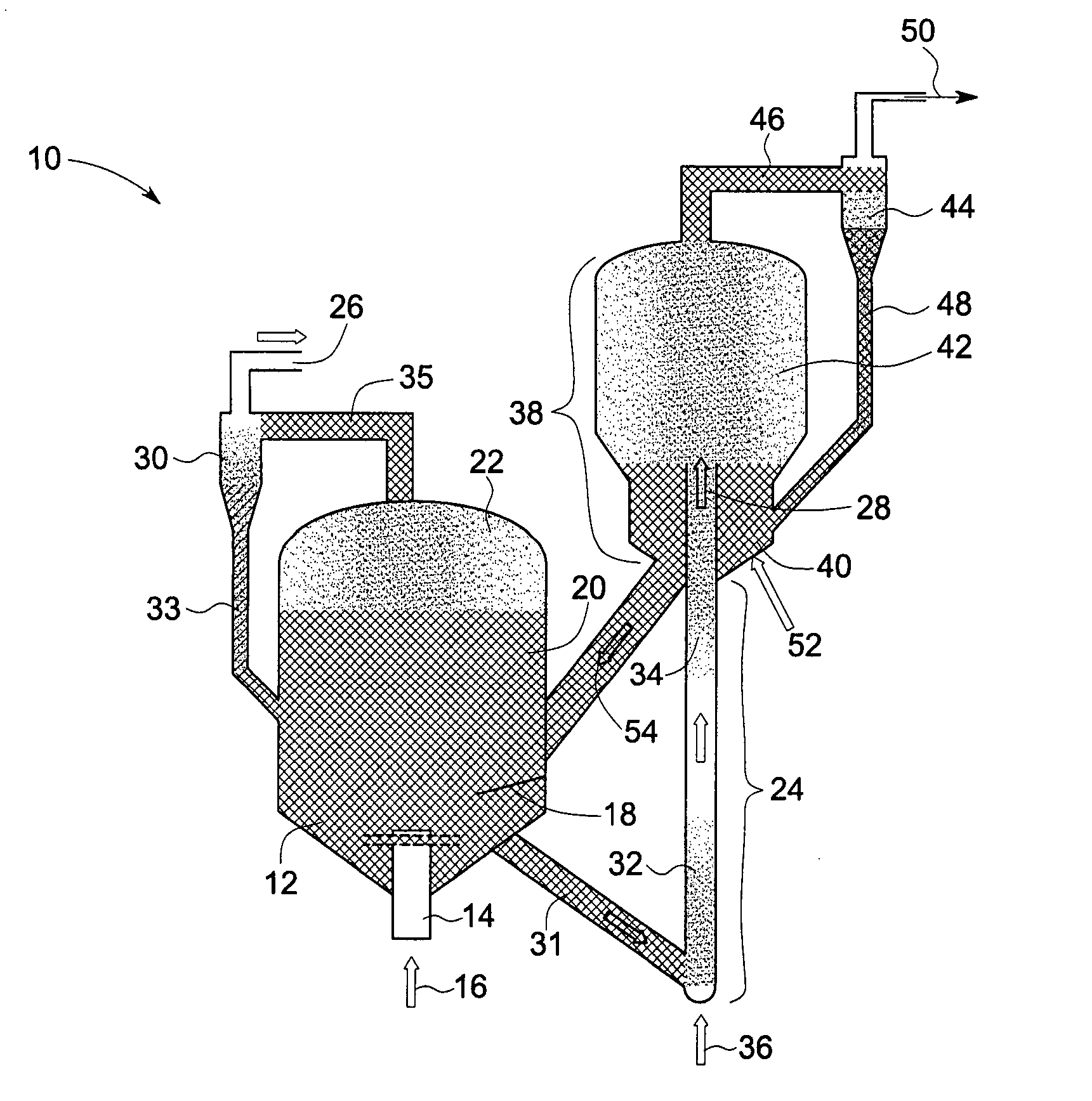
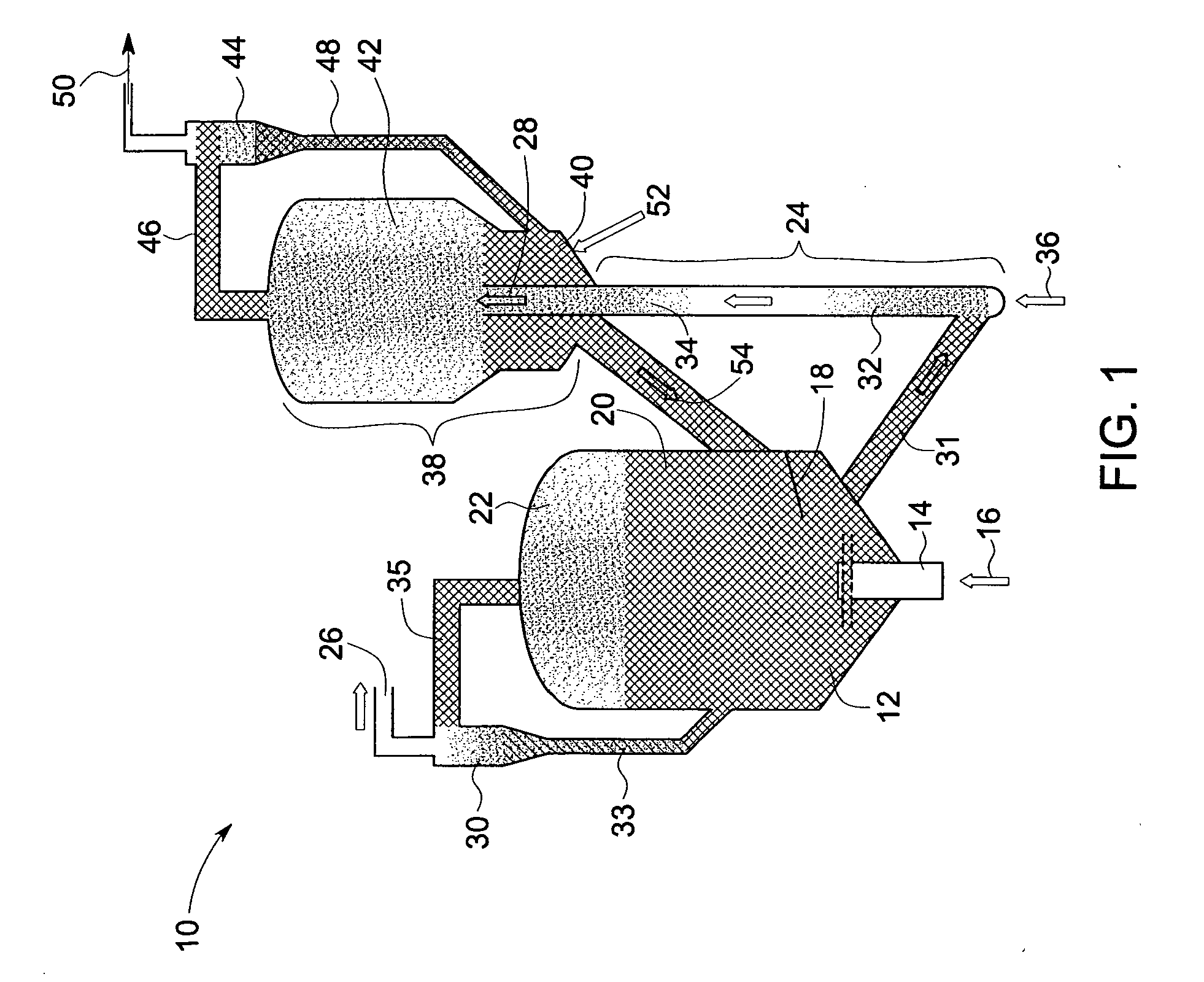
[0014]FIG. 1 represents an exemplary system 10 for producing synthesis gas. The system 10 includes a regeneration zone 12 and a mixed reforming zone 24. The regeneration zone 12 includes a first fluidized bed 20 configured to receive an oxidant 16 for producing a regenerated oxygen transfer material (OTM). The mixed reforming zone 24 includes a second fluidized bed configured to receive a fuel 36 (natural gas or liquid fuels), with a portion of steam and the regenerated OTM to produce a first reformate stream 28. The steam may be mixed with the fuel 36 as shown in FIG. 1 or it can be introduced in the mixed reforming zone 24 separately. The system 10 further includes a steam-reforming zone 38. The steam reforming zone 38 comprises a third fluidized bed that includes a dilute bed 42, which dilute bed 42 has a low density of the particulates and a dense bed 40 with a high density of particulates. The third fluidized bed 38 is configured to receive the first reformate stream 28, and st...


PUM

PropertyMeasurementUnit
particle sizesaaaaaaaaaa
sizeaaaaaaaaaa

Abstract

A system for producing synthesis gas includes a regeneration zone. The regeneration zone includes a first fluidized bed configured to receive an oxidant for producing a regenerated oxygen transfer material. The system further includes a mixed reforming zone comprising a second fluidized bed configured to receive a first fuel and the regenerated oxygen transfer material to produce a first reformate stream and a steam reforming zone comprising a third fluidized bed configured to receive the first reformate stream, a second fuel and steam to produce the synthesis gas. The regeneration zone, mixed reforming zone and steam-reforming zone are in fluid communication with each other.

Description

BACKGROUND OF THE INVENTION [0001] This invention relates to systems and methods for producing synthesis gas. More particularly, this invention relates to systems and methods for producing synthesis gas using fluidized bed reactors without an Air Separation Unit (ASU). [0002] Currently complex industrial plants are built around the globe to produce synthesis gases for use in a variety of applications including conversion of natural gas to useful liquid fuels in a Gas-To-Liquids (GTL) plant, generation of hydrogen gases and other processes. The ASU is typically an integral part of a GTL plant and costs about one third of the capital cost of a GTL plant. Therefore one challenge faced by these complex industrial plants is how to eliminate or reduce the capital expenditure that is required to build ASU in those plants. [0003] Liquid hydrocarbons for fueling different types of engines can be synthesized in Gas-to-Liquid (GTL) plants in which synthesis gas (a mixture of CO and H2) is cata...

Claims


Application Information

Patent Timeline
Patent Type & Authority Applications(United States)
IPC IPC(8): C01B3/32F27B15/00
CPCB01J8/0055B01J8/28B01J23/94B01J23/96B01J38/30B01J2208/00672B01J2208/025B01J2219/0077C01B3/44C01B3/56C01B2203/0233C01B2203/0244C01B2203/0261C01B2203/0288C01B2203/0415C01B2203/0425C01B2203/0475C01B2203/062C01B2203/0838C01B2203/84Y02P20/52Y02P20/584
Inventor LIU, KEZAMANSKY, VLADIMIR
Owner AIR PROD & CHEM INC
Why Eureka
Try Eureka