Microcombustors, microreformers, and methods for combusting and for reforming fluids

a micro-combustion and micro-reformer technology, applied in the direction of combustion types, sustainable manufacturing/processing, furnaces, etc., can solve the problems of difficult heat generation of endothermic reforming processes, low energy density of current battery technology, and inability to provide stable heat for endothermic reforming processes. achieve the effect of desirable performance capability

Inactive Publication Date: 2006-07-18
BATTELLE MEMORIAL INST
View PDF51 Cites 55 Cited by
  • Summary
  • Abstract
  • Description
  • Claims
  • Application Information

AI Technical Summary

Benefits of technology

[0099]A significant advantage of the present invention is the ability to provide microcombustors and microreformers, possessing desirable performance capability, in sizes that have been heretofore unobtainable. Surprisingly, in methods and devices of the present invention, these small sizes can be accompanied by self-sustaining or better performance. The various combinations of size, flow rates, performance, and other variables discussed herein are preferred characteristics that can be used to describe the present invention.
[0100]Alcohol conversion is preferably at least 50%, more preferably at least 80% and still more preferably at least 90%. We have achieved greater than 99% conversion with thermal efficiencies (as defined below) of about 10%. Hydrogen selectivity, defined as moles H atoms in H2 in the product gas divided by moles H in all product gases, is preferably at least 50%, more preferably at least 60%, still more preferably at least 85%. A conversion higher than 99% and close to 100% for fuels to both the combustor and for the reformer has been attained.
[0101]In the combustion chamber conversion (as measured by gas chromatography of the exhaust gas) is preferably at least 70%, more preferably at least 80%, and still more preferably at least 90% and still more preferably at least 95%. Carbon dioxide selectivity, defined as moles CO2 in the exhaust gas divided by of all carbon-and-oxygen-containing product gases, is preferably at least 50%, more preferably at least 70%, still more preferably at least 85%. Thermal effic

Problems solved by technology

However, current battery technology has a very low energy density, on the order of from 0.035 to 0.350 kWe-hr/kg.
This is difficult because the combustion and, therefore, the reforming processes are no longer stable.
However, providing stable heat for the endothermic reforming processes is difficult, due to the fact that stable combustion is

Method used


Image

  • Microcombustors, microreformers, and methods for combusting and for reforming fluids
  • Microcombustors, microreformers, and methods for combusting and for reforming fluids
  • Microcombustors, microreformers, and methods for combusting and for reforming fluids

Examples


example

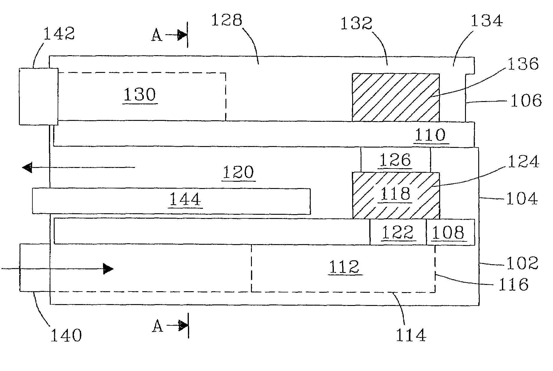
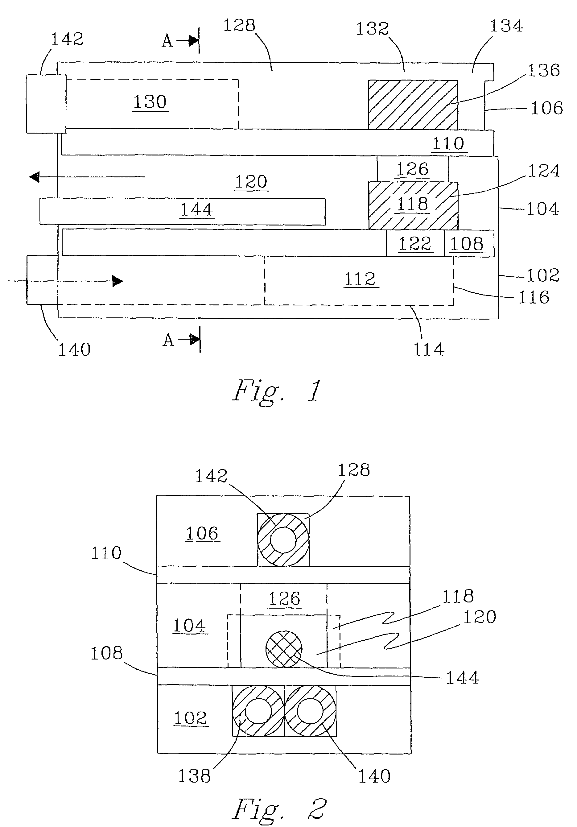
[0105]An integrated fuel processor system composed of two vaporizers / preheaters, a reformer, catalytic combustor, and heat exchanger was built and tested. For each of these designs the manufacture and assembly were performed in the same fashion. Metal pieces were cut and machined from standard stainless steel stock. Ceramic pieces were formed and machined using standard ceramics molding and shaping techniques. Tubing and fittings were cut to fit as required.

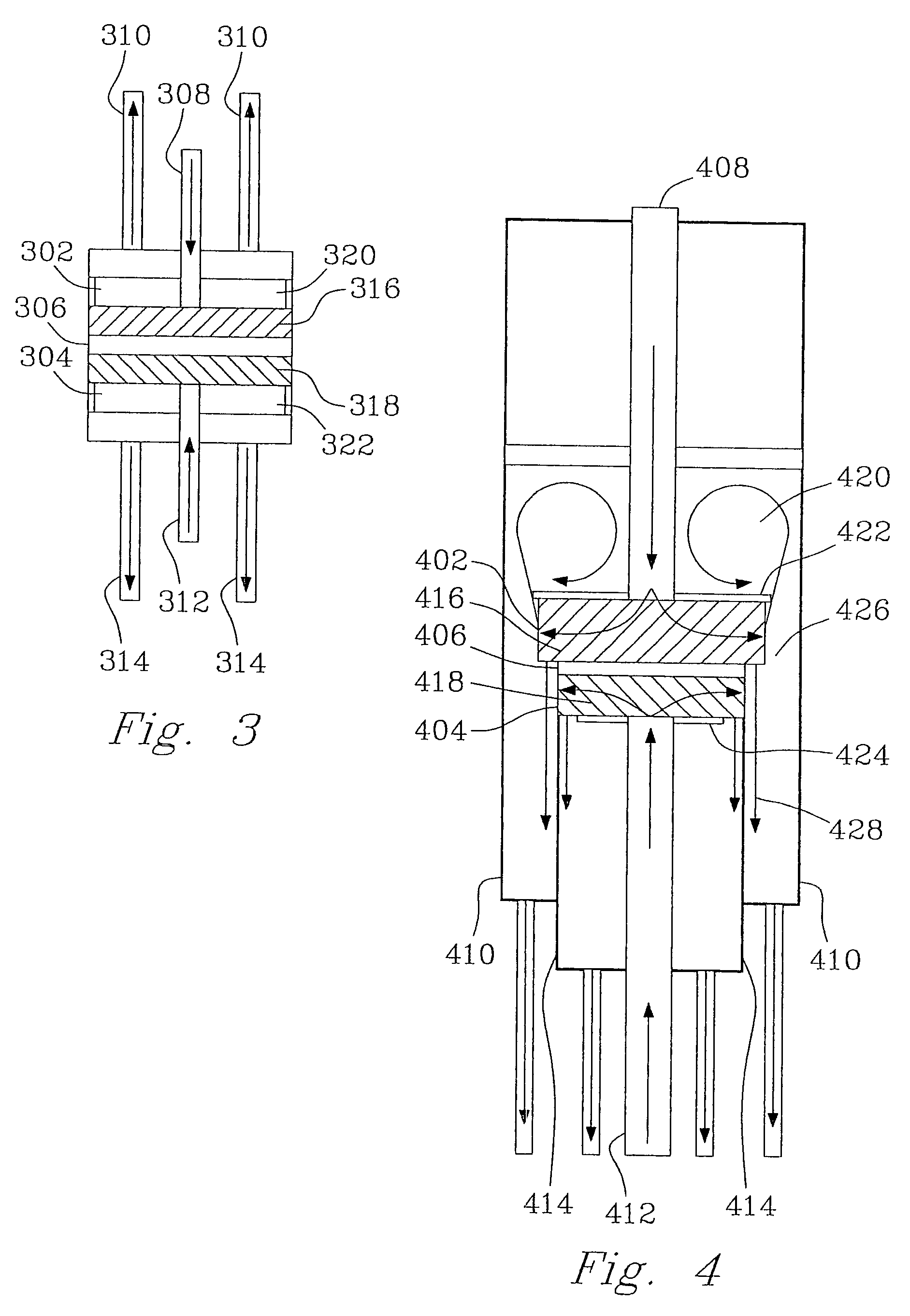
[0106]The following example is for a device such as illustrated in FIG. 3. For preassembly, all of the tubing, catalyst pieces, and respective reactor parts were cut per specifications. Plungers were joined to tubing using standard, high-temperature adhesives. In the alternative, high-temperature soldering could be used for some or all joins. All tubing and the plunger assemblies were inserted through the end-caps or end-seals and set to their appropriate positions for final assembly.

[0107]The first step in the assembly process w...


PUM

PropertyMeasurementUnit
Temperatureaaaaaaaaaa
Fractionaaaaaaaaaa
Fractionaaaaaaaaaa

Abstract

The present invention provides microcombustors, microreformers, and methods of steam reforming alcohols over a catalyst. The microcombustors can be manufactured with a very small size and can operate at very low temperature. Surprisingly superior results and properties obtained in methods of the present invention are also described.

Description

[0001]This invention was made with Government support under DARPA contract# DABT63-99-C-0039. The Government has certain rights in this invention.FIELD OF THE INVENTION[0002]The invention relates to combustors and steam reformers, and methods for combusting and steam reforming fuels.BACKGROUND OF THE INVENTION[0003]The ever-decreasing size of microelectronic devices and the rapid development of microelectromechanical systems (MEMS) have created a great need for high energy density micropower supplies, for example, a power supply for microelectronic devices. Typically, conventional battery technology is used in these applications. However, current battery technology has a very low energy density, on the order of from 0.035 to 0.350 kWe-hr / kg. An alternative to batteries is to combine a small fuel cell with a micro-hydrocarbon fuel processor. In this case, the size of a fuel processor's primary converter, e.g., fuel reformer, must be reduced. It is also desirable to lower the operatin...

Claims


Application Information

Patent Timeline
IPC IPC(8): F23D11/44B01J19/00C01B3/38F23D99/00H01M8/04H01M8/06
CPCB01J19/0093C01B3/384F23D99/003H01M8/04022H01M8/0618H01M8/0662Y02E60/50B01J2219/00835B01J2219/00862B01J2219/00873B01J2219/00891C01B2203/0227C01B2203/066C01B2203/0811C01B2203/0822F23C2900/03001B01J2219/00783F23D91/02Y02P20/10Y02P70/50
Inventor HOLLADAY, JAMELYN D.PHELPS, MAX R.WANG, YONGCHIN, YA-HUEI
Owner BATTELLE MEMORIAL INST
Why Eureka
Try Eureka