Microcombustors, microreformers, and methods involving combusting or reforming fluids

a micro-combustion and reformer technology, applied in the direction of combustion type, physical/chemical process catalyst, combustion of catalytic materials, etc., can solve the problems of low energy density of current battery technology, many fuel cells require hydrogen gas having very low levels of carbon monoxide (co) contamination, and achieve conversion and/or thermal efficiency reduction, the effect of desirable performance capability

Active Publication Date: 2009-09-08
BATTELLE MEMORIAL INST
View PDF22 Cites 3 Cited by
  • Summary
  • Abstract
  • Description
  • Claims
  • Application Information

AI Technical Summary

Benefits of technology

[0108]A significant advantage of the present invention is the ability to provide microcombustors and microreformers, possessing desirable performance capability, in sizes that have been heretofore unobtainable. Surprisingly, in methods and devices of the present invention, these small sizes can be accompanied by self-sustaining or better performance. The various combinations of size, flow rates, performance, and other variables discussed herein are preferred characteristics that can be used to describe the present invention. The characteristics described in the Operating Conditions section and the following levels of conversions and / or selectivities and / or thermal gradients and / or thermal efficiencies and / or stabilities are characteristics of some preferred inventive methods. These levels are also characteristic of apparatus when it is tested under the following conditions: when H2O and methanol in a 1.2:1 molar ratio are feed into the reforming chamber with a contact time of 1.0 second, and fuel and oxygen are combusted in the combustion chamber at a rate sufficient to obtain an average temperature of 320° C. within the combustion chamber. Preferably, in this test, hydrogen and air are combusted with a feed ratio comprising a H2:O2 ratio of 0.5.
[0109]Alcohol conversion in the reforming channel is preferably at least 50%, more preferably at least 80% and still more preferably at least 90%, and yet more preferably at least 98%. Hydrogen selectivity, defined as moles H atoms in H2 in the product gas divided by moles H in all product gases, is preferably at least 50%, more preferably at least 60%, still more preferably at least 85%. H2:CO ratio in the product stream is preferably at least 70, more preferably at least 100; and still more preferably at least 10,000, and in some embodiments in the range of 100 to 100,000.
[0110]In the combustion chamber, fuel conversion (as measured by gas chromatography of the exhaust gas) is preferably at least 70%, more preferably at least 80%, and still more preferably at least 90% and still more preferably at least 98%. Carbon dioxide selectivity, defined as moles CO2 in the exhaust gas divided by of all carbon-and-oxygen-containing product gases, is preferably at least 50%, more preferably at least 70%, still more preferably at least 85%. Conversions higher than 99% and close to 100% for fuels to both the combustor and for the reformer has been attained.
[0111]In some embodiments, the reforming chamber is hottest at one end, and gets cooler along its length. In some preferred embodiments, the temperature at one end of the length of a reforming chamber is within 20° C. of the temperature of the combustion chamber, and that hot end is at least 10° C. higher than the average temperature of the reforming catalyst.
[0112]Thermal efficiency is preferably at least 5%, more preferably at least 10% and still more preferably at least about 20%, and in some embodiments 10 to about 35%, in some embodiments 15 to 25%.
[0113]The systems preferably are stable such that conversion and / or thermal efficiency decreases by 5% or less after 100 hours of continuous operation, and, preferably, degrades by 5% or less after 5 thermal cycles. Whether a system “degrades” can be defined (and measured) using any of the properties and characteristics discussed herein, for example, alcohol conversion, H2 production, and / or CO levels.

Problems solved by technology

However, current battery technology has a very low energy density, on the order of from 0.035 to 0.350 kWe-hr / kg.
However, thus far, it has not been possible to construct a very small, thermally efficient fuel reformer.
An additional problem is that many fuel cells require hydrogen gas having very low levels of carbon monoxide (CO) contamination.
Another problem is that instability in microcombustor operation can lead to partial vaporization of the hydrocarbon fuel, if it is liquid, and to less than desired conversion of the hydrocarbons to a hydrogen rich product stream due to the intermittent lack of energy for the endothermic reactions.
The prior art processes for reforming hydrocarbons to produce hydrogen suitable for a fuel cell typically require multiple step operations in large and complex apparatus.

Method used


Image

  • Microcombustors, microreformers, and methods involving combusting or reforming fluids
  • Microcombustors, microreformers, and methods involving combusting or reforming fluids
  • Microcombustors, microreformers, and methods involving combusting or reforming fluids

Examples


example 1

[0137]An integrated fuel processor system composed of two vaporizers / preheaters, a reformer, catalytic combustor, and heat exchanger was built and tested. For each of these designs the manufacture and assembly were performed in the same fashion. Metal pieces were cut and machined from standard stainless steel stock. Ceramic pieces were formed and machined using standard ceramics molding and shaping techniques. Tubing and fittings were cut to fit as required.

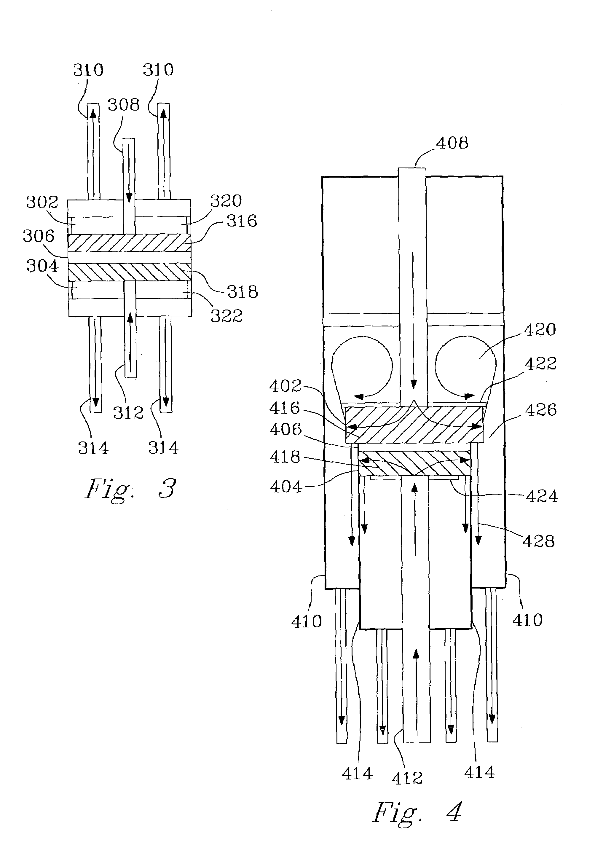
[0138]The following example is for a device such as illustrated in FIG. 3. For preassembly, all of the tubing, catalyst pieces, and respective reactor parts were cut per specifications. Plungers were joined to tubing using standard, high-temperature adhesives. In the alternative, high-temperature soldering could be used for some or all joins. All tubing and the plunger assemblies were inserted through the end-caps or end-seals and set to their appropriate positions for final assembly.

[0139]The first step in the assembly process w...

example 2

[0148]The device illustrated in FIG. 7 was fabricated similarly to the descriptions in Example 1. The combustion catalyst was Pt on alumina that was coated onto a FeCrAlY felt support. On the reforming side of the device, a porous reforming catalyst felt was inserted into the channel. The diameter of the felt (0.26 inch, 0.66 cm) was the same as the inner diameter of the cylinder. Then, a porous plunger (having a center hole through the center with an inlet tube through the hole) was pressed onto the catalyst felt. In this case, the porous plunger was also a porous reforming catalyst felt. Prior to insertion, a laser was used to form a hole in the center of the porous plunger. Alternative techniques such as punching a hole through a felt prior to depositing a catalyst coating may alternatively be used. The reforming catalyst felts were prepared by coating a FeCrAlY felt with alumina followed by depositing Pd.

[0149]Then, 16 mg of a steam reforming powder catalyst was poured in. This ...


PUM

PropertyMeasurementUnit
temperatureaaaaaaaaaa
volumeaaaaaaaaaa
molar ratioaaaaaaaaaa

Abstract

The invention describes combustors and steam reformers and methods of combustion and steam reforming. For example, integrated combustion reactors are described in which heat from combustion is transferred to an endothermic reaction. Thermally efficient reactors and methods of alcohol steam reforming are also described. Also described is an integrated combustor/reformer containing a methanation catalyst.

Description

RELATED APPLICATIONS[0001]This application is a continuation-in-part of U.S. patent application No. 10 / 008,363, filed Nov. 7, 2001, now U.S. Pat. No. 7,077,643.[0002]This invention was made with Government support under DARPA contract # DABT63-99-C-0039. The Government has certain rights in this invention.FIELD OF THE INVENTION[0003]The invention relates to combustors and steam reformers, and methods involving combusting or steam reforming.BACKGROUND OF THE INVENTION[0004]The ever-decreasing size of microelectronic devices and the rapid development of microelectromechanical systems (MEMS) have created a great need for high energy density micropower supplies, for example, a power supply for microelectronic devices. Typically, conventional battery technology is used in these applications. However, current battery technology has a very low energy density, on the order of from 0.035 to 0.350 kWe-hr / kg. An alternative to batteries is to combine a small fuel cell with a micro-hydrocarbon ...

Claims


Application Information

Patent Timeline
Patent Type & Authority Patents(United States)
IPC IPC(8): B01J8/04B01J19/00B01J21/04B01J21/06B01J23/60B01J23/63B01J37/03C01B3/32C01B3/38F23C13/00
CPCB01J19/0093B01J23/60B01J23/63B01J37/03C01B3/323C01B3/384F23C13/00F23C2900/03001B01J21/066B01J2219/00783B01J2219/00833B01J2219/00835B01J2219/00873B01J2219/00891C01B2203/00C01B2203/0233C01B2203/04C01B2203/0445C01B2203/047C01B2203/066C01B2203/0811C01B2203/0816C01B2203/0822C01B2203/0827C01B2203/1011C01B2203/1052C01B2203/1064C01B2203/1076C01B2203/1082C01B2203/1217C01B2203/1223C01B2203/1288C01B2203/1619B01J21/04Y02P20/52Y02P20/10
Inventor HOLLADAY, JAMELYN D.WANG, YONGHU, JIANLICHIN, YA-HUEIDAGLE, ROBERT A.XIA, GUANGUANGBAKER, EDDIE G.PALO, DANIEL R.PHELPS, MAXJUNG, HEON
Owner BATTELLE MEMORIAL INST
Why Eureka
Try Eureka