Device for transfer of heat

a technology of heat transfer device and heat transfer device, which is applied in the direction of domestic cooling device, lighting and heating device, cooling/ventilation/heating modification, etc., can solve the problems of reducing cooling efficiency, and affecting the cooling effect of electronics

Inactive Publication Date: 2007-06-07
ELTEK VALERE AS
View PDF13 Cites 11 Cited by
  • Summary
  • Abstract
  • Description
  • Claims
  • Application Information

AI Technical Summary

Problems solved by technology

This requirement of accessibility implies distinct limitations as to integrating the climate plant with the electronics.
This leads to a reduction in cooling efficiency and increases the temperature of the air intended for the cooling of the electronics.
A temperature increase of air intended for cooling may lead reduction of functions, breakdown in production or damages of the electronics.
To avoid this reduction in heat exchange efficiency some systems are equipped with connecting parts between the electronics and the climate system, and the risk for leakage between the parts is increased.
These type of systems are complicated with a lot of tubing, and leakage in these cases will lead to the above mentioned problems.
These types of systems with several parts located in different ways on different portions in the cabinet, which parts simultaneously have to be connected and function correctly together, become very voluminous, require a lot of mechanic parts, are difficult to standardize, require specific adaptation and are expensive.

Method used


Image

  • Device for transfer of heat
  • Device for transfer of heat
  • Device for transfer of heat

Examples


Embodiment Construction

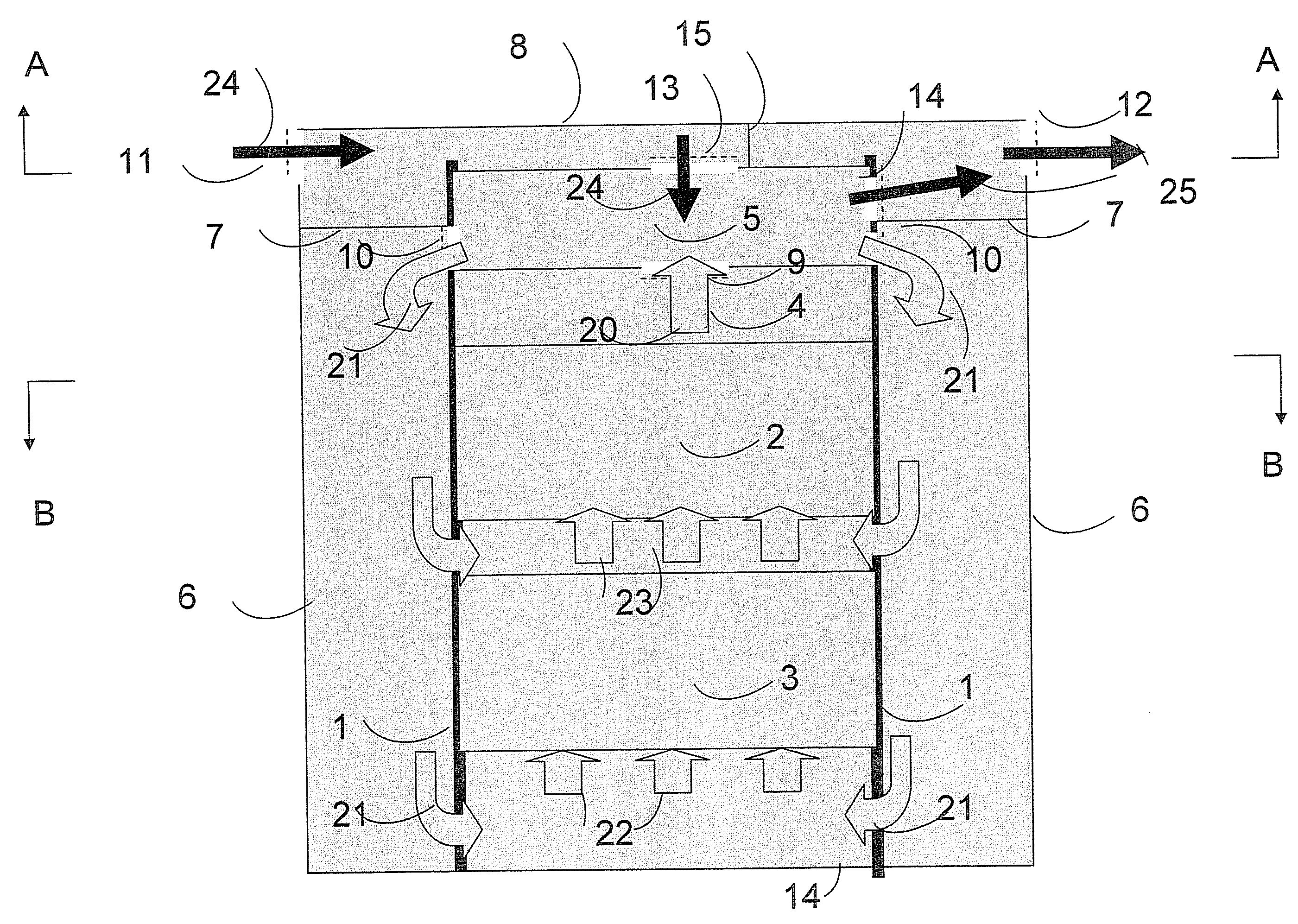
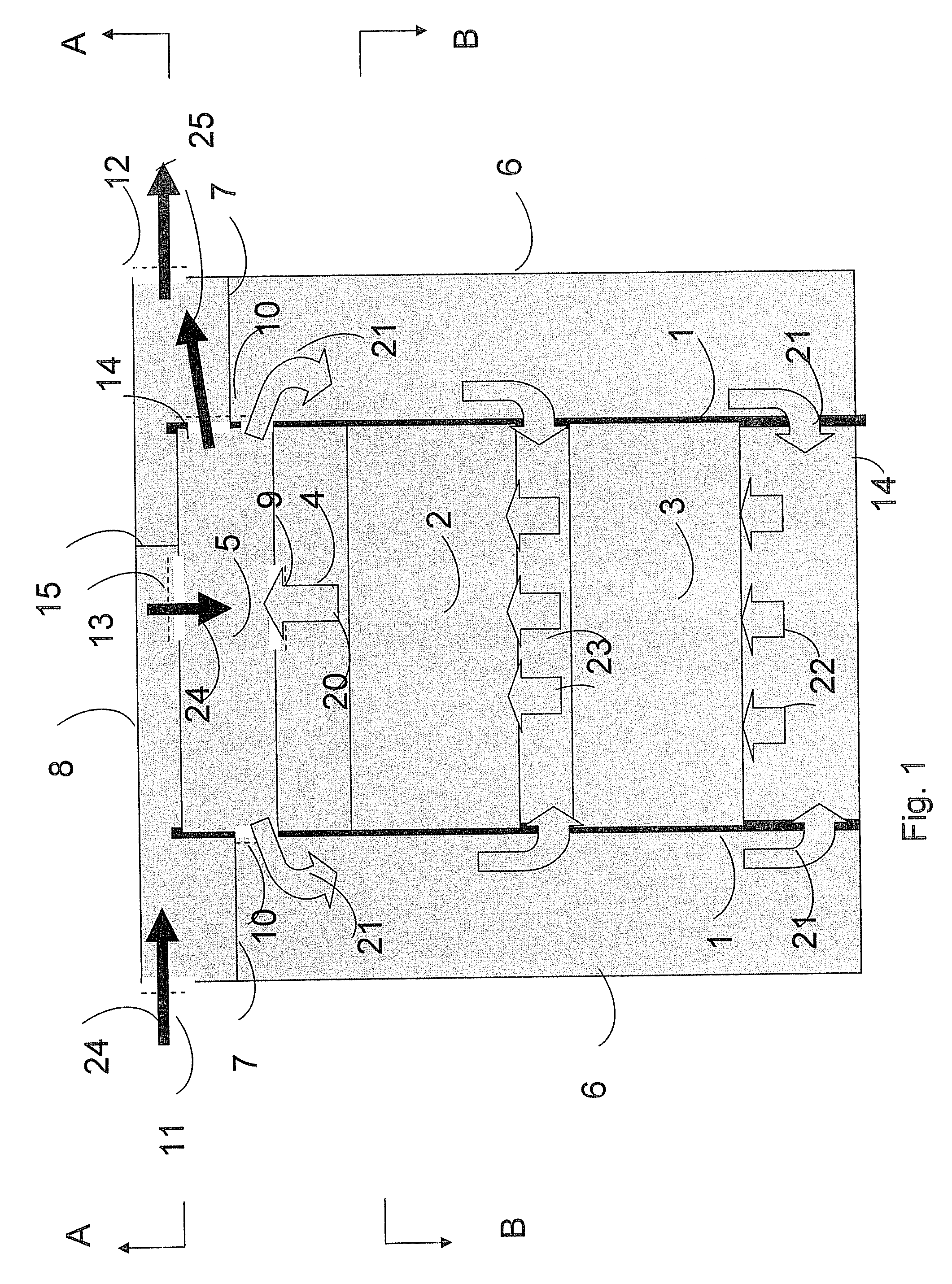
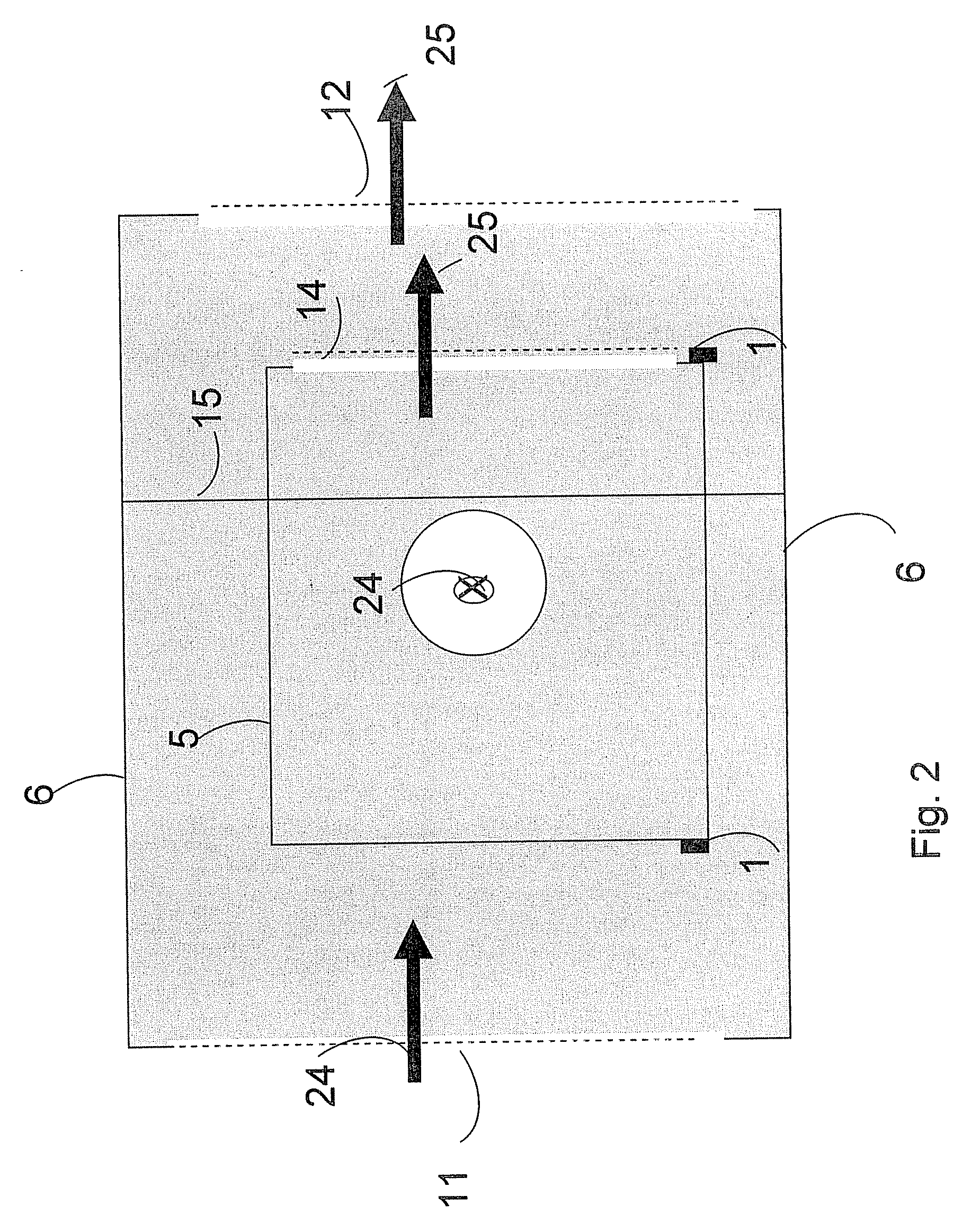
[0017] In FIG. 1 one embodiment of a structure for electronics in outdoor cabinets, with the present invention implemented, is shown. Said structure comprises an outdoor cabinet 100, a climate unit 5, a collection chamber 4 and electronic units 2 and 3, which components are mounted in a rack system comprising vertical support beams 1 in the outdoor cabinet 100. The outdoor cabinet 100 is formed by a bottom 16, walls 6 and a roof 8.

[0018] The climate unit 5 takes an airflow 20 through openings 9 in the climate unit 5. Said air is cooled in the climate unit 5 and exits as air flows 21 through outlet openings 10 of the climate unit. The airflow 21 flows through openings in vertical support beams 1 and into the electronics unit 3 at the bottom of the rack system. Airflow is caused to be distributed into spread flows 22 as it enters unit 3 according to a method known for structures intended for electronics for e.g. telecom. Said spread flows 22 exit the top of unit 3, and are further tr...


PUM


Abstract

A structure for housing electronic equipment, for example outdoor telecom applications such as radio base stations, in a climate-controlled environment. The structure comprises a compact climate-control unit adapted for integration into the structure. The climate system provides for circulation of air in an internal closed circuit for cooling of heat generated by the electronic units within a closed space within the interior of the structure.

Description

[0001] This application claims the benefit under 35 USC § 119(e) to Provisional application 60 / 708,770 filed 17 Aug. 2005 and Provisional application 60 / 709,133 filed 18 Aug. 2005.BACKGROUND Field of the invention [0002] The present invention relates to a simplified structure for preferably outdoor telecom applications, e.g. radio base stations. The simplified structure comprises a compact climate system adapted for integration into a fundamental structure for electronics. BACKGROUND [0003] As will be obvious for a man skilled in the art, the climate system has as a function to transport heat from the inner space of the outdoor cabinet to the outdoor ambient. It need not only be meant for cooling of electronic equipment but all kinds of heat exchange are conceivable. [0004] The invention is a further development of the device described in WO 92 / 18821, the teachings of which are hereby incorporated by reference. [0005] The conventional structures of today for outdoor cabinets for tel...

Claims


Application Information

Patent Timeline
Patent Type & Authority Applications(United States)
IPC IPC(8): F25D23/12
CPCH05K7/20009
Inventor GUDMUNDSSON, BJORNGUDMUNDSSON, MAGNUS
Owner ELTEK VALERE AS
Why Eureka
Try Eureka