Anesthesia ventilator system including manual ventilation

a ventilation system and anesthesia technology, applied in the field of ventilation systems, can solve the problem of pressure maintaining within

Active Publication Date: 2007-06-07
GENERAL ELECTRIC CO
View PDF1 Cites 86 Cited by
  • Summary
  • Abstract
  • Description
  • Claims
  • Application Information

AI Technical Summary

Benefits of technology

[0012] During the exhalation phase, an exhalation valve is opened to allow the patient to exhale until the exhalation pressure falls to the PEEP pressure. At the same time, the manual ventilation bag is being filled by the inhalation gas flow such that the manual ventilation bag can be utilized during the next ventilation cycle. The control system of the present invention b

Problems solved by technology

However, due to the mass of the manual bag, pressur

Method used


Image

  • Anesthesia ventilator system including manual ventilation
  • Anesthesia ventilator system including manual ventilation
  • Anesthesia ventilator system including manual ventilation

Examples


Embodiment Construction

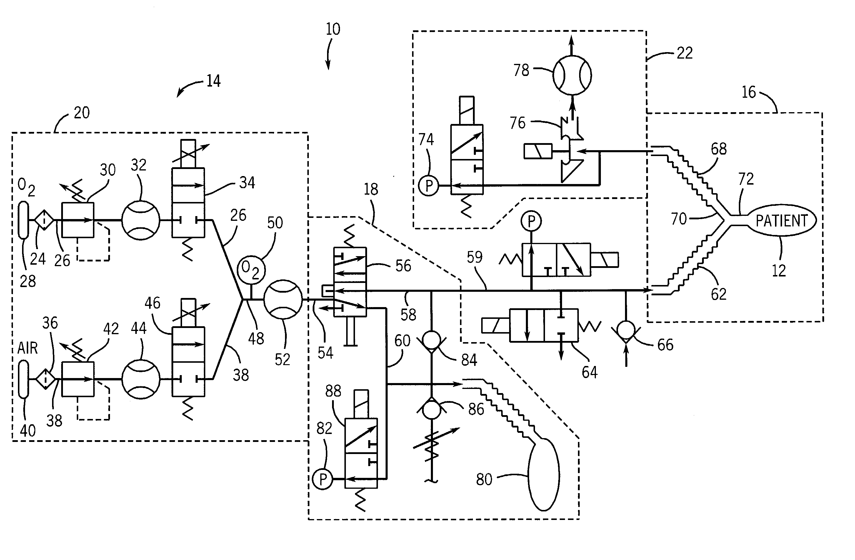
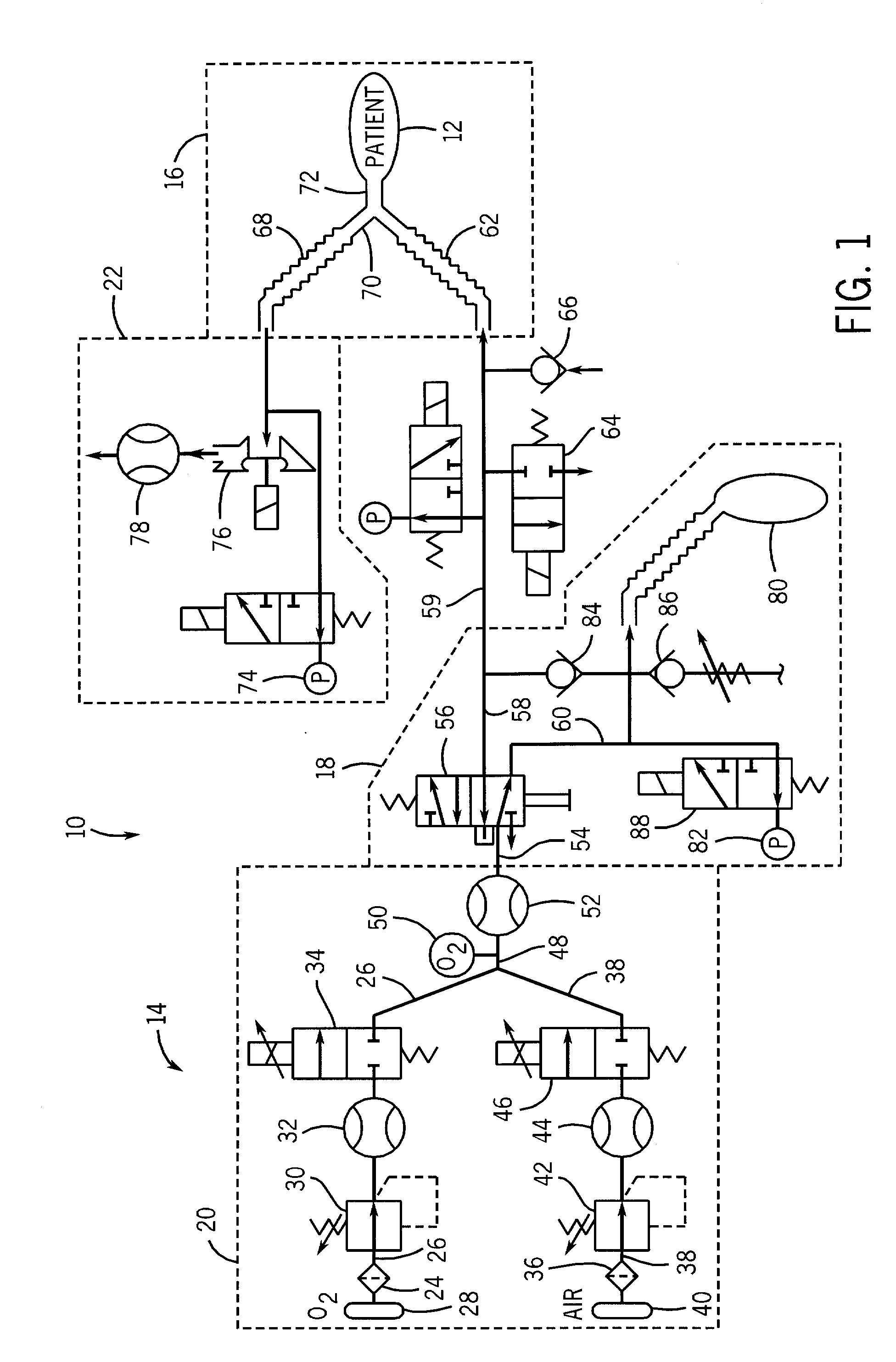
[0016] A ventilation system 10 is shown in FIG. 1 for providing an inhalation gas to a patient 12 for use in intensified breathing. The ventilation system of the present invention is particularly useful whenever the patient 12 is receiving intravenous anesthesia.

[0017] The ventilation system 10 generally includes a ventilator 14, a patient breathing circuit 16 and a manual ventilation circuit 18. The ventilator 14 generally comprises a gas supply system 20 and an exhalation control system 22 that are each controlled by a control system (not shown) of the ventilator 14.

[0018] As illustrated in FIG. 1, the gas supply system 20 includes a compressed oxygen interface 24, including a compressed oxygen conduit 26 connected to a compressed oxygen tank 28. The oxygen conduit 26 includes a pressure regulator 30, a gas flow sensor 32 and a flow control valve 34. The flow sensor 32 and flow control valve 34 are each coupled to the control system for the ventilator 14 such that the ventilator...


PUM


Abstract

A ventilation system for intensified breathing that includes both a manual ventilation system and automatic ventilation system. The gas mixture from a gas supply system is supplied to a switching valve that is operable between a manual position and an automatic position. When the switching valve is in the manual position, the inhalation gas from the supply system is guided to a manual ventilation bag. When the ventilation bag is squeezed during manual inhalation, the gas flow from the manual bag is directed to the inhalation limb of the patient circuit. When the manual ventilation bag is released, the pressure within the ventilation bag falls below the exhalation pressure, thereby indicating the beginning of the exhalation phase and the re-inflation of the manual ventilation.

Description

BACKGROUND OF THE INVENTION [0001] The present invention generally relates to a ventilation system for use in intensified breathing. More specifically, the present invention relates to an anesthesia ventilation system used during surgical operations where anesthesia is being delivered to a patient through an intravenous line where the ventilation system includes both an automatic ventilation system and a manual ventilation system. [0002] Presently, anesthesia machines are optimized for delivering anesthesia to a patient using volatile anesthetic agent liquids. In such systems, the anesthetic agent is vaporized and mixed into the breathing gas stream in a controlled manner to provide a gas mixture for anesthetizing the patient for a surgical operation. The most common volatile anesthetic agents are halogenated hydrocarbon chains, such as halothane, enflurane, isoflurane, sevoflurane, and desflurane. Additionally, nitrous oxide (N2O) can be counted in this group of volatile anesthetic...

Claims


Application Information

Patent Timeline
IPC IPC(8): A61M16/00
CPCA61M16/0078A61M16/01A61M16/12A61M16/20A61M2016/0027A61M2016/0039A61M2016/0042A61M2016/1025A61M2202/0208A61M2205/3331A61M2205/70A61M16/0084A61M16/203A61M16/205A61M16/209A61M16/204
Inventor HEINONEN, ERKKIBROMSTER, LEIF
Owner GENERAL ELECTRIC CO
Why Eureka
Try Eureka