Pneumatic tire

a technology of pneumatic tires and tires, applied in the field of pneumatic tires, can solve the problems of reducing the cornering capability of tires, non-uniform shape, and detrimental to tire performance, and achieve the effect of improving tire performan

Inactive Publication Date: 2007-06-07
POLING DAVID CHARLES +9
View PDF11 Cites 6 Cited by
  • Summary
  • Abstract
  • Description
  • Claims
  • Application Information

AI Technical Summary

Benefits of technology

[0003] The present invention is directed to a tire designed to compensate for wheel cambering and yield improved tire performance.

Problems solved by technology

Roll and lateral deflection to the outside tend to lift this inside shoulder, reducing the tire's cornering capability.
Given the fact that both sides of a tire are generally equal, this causes an asymmetric loading of the footprint leading to a side-to-side non-uniform shape that can be detrimental to the tire performance.

Method used


Image

  • Pneumatic tire
  • Pneumatic tire
  • Pneumatic tire

Examples


Embodiment Construction

[0034] The following language is of the best presently contemplated mode or modes of carrying out the invention. This description is made for the purpose of illustrating the general principles of the invention and should not be taken in a limiting sense. The scope of the invention is best determined by reference to the appended claims.

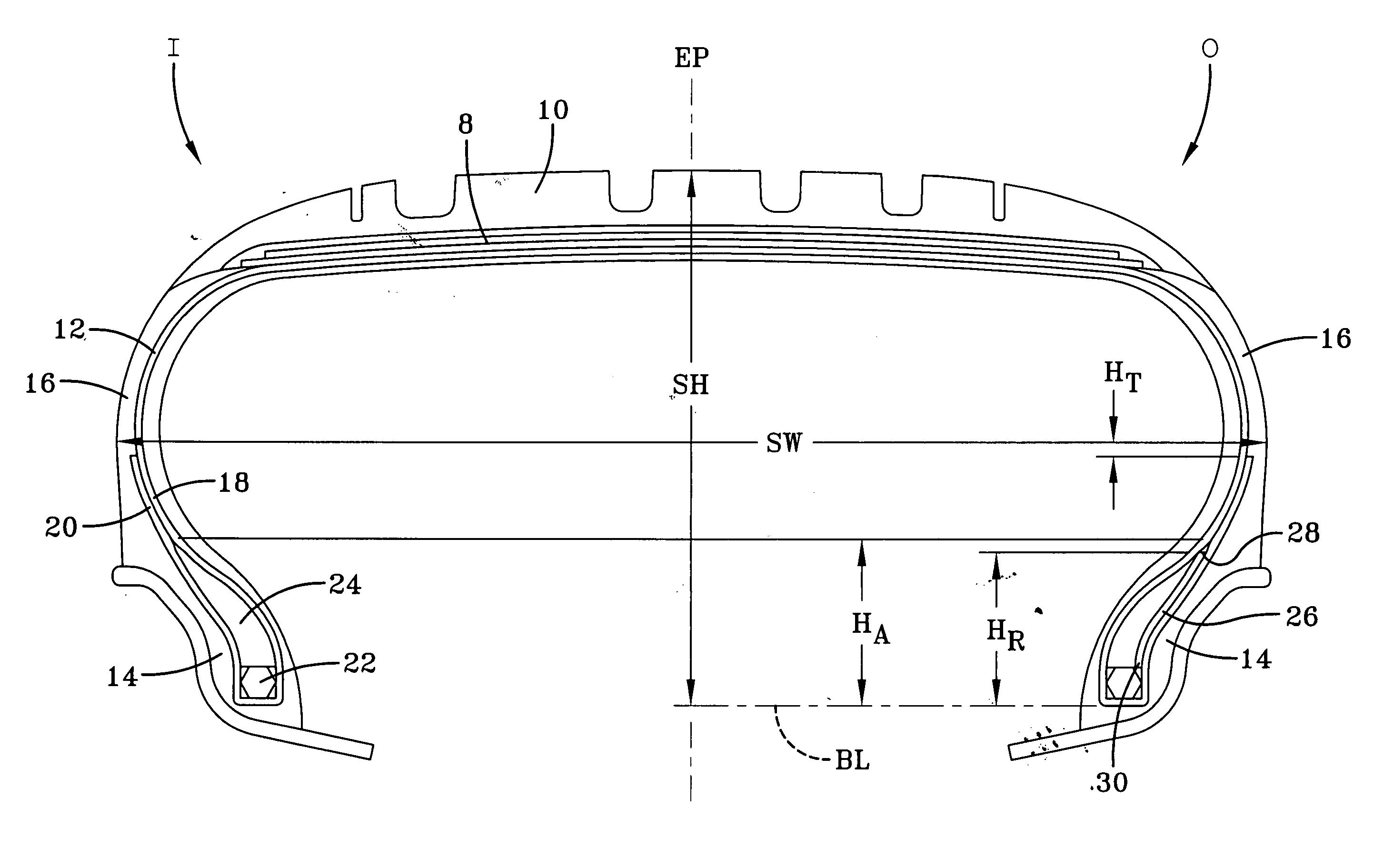
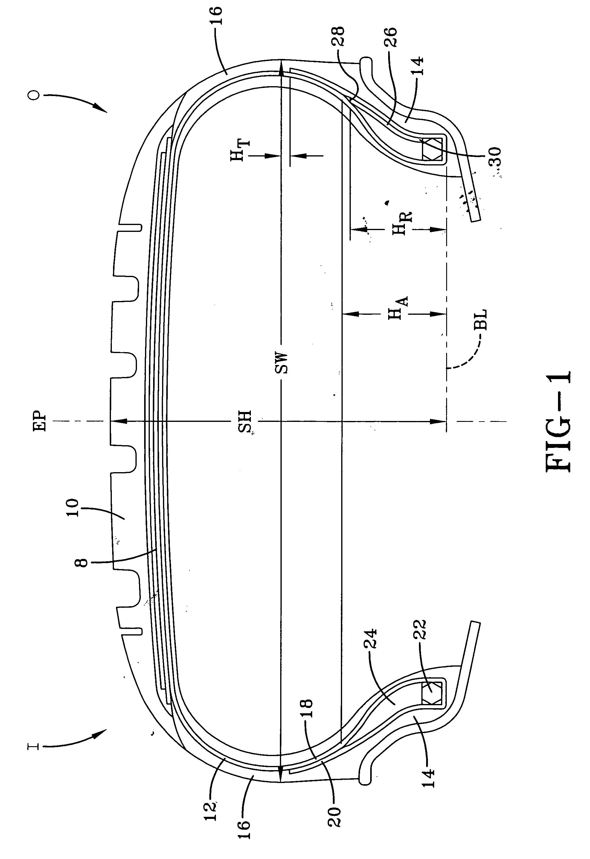
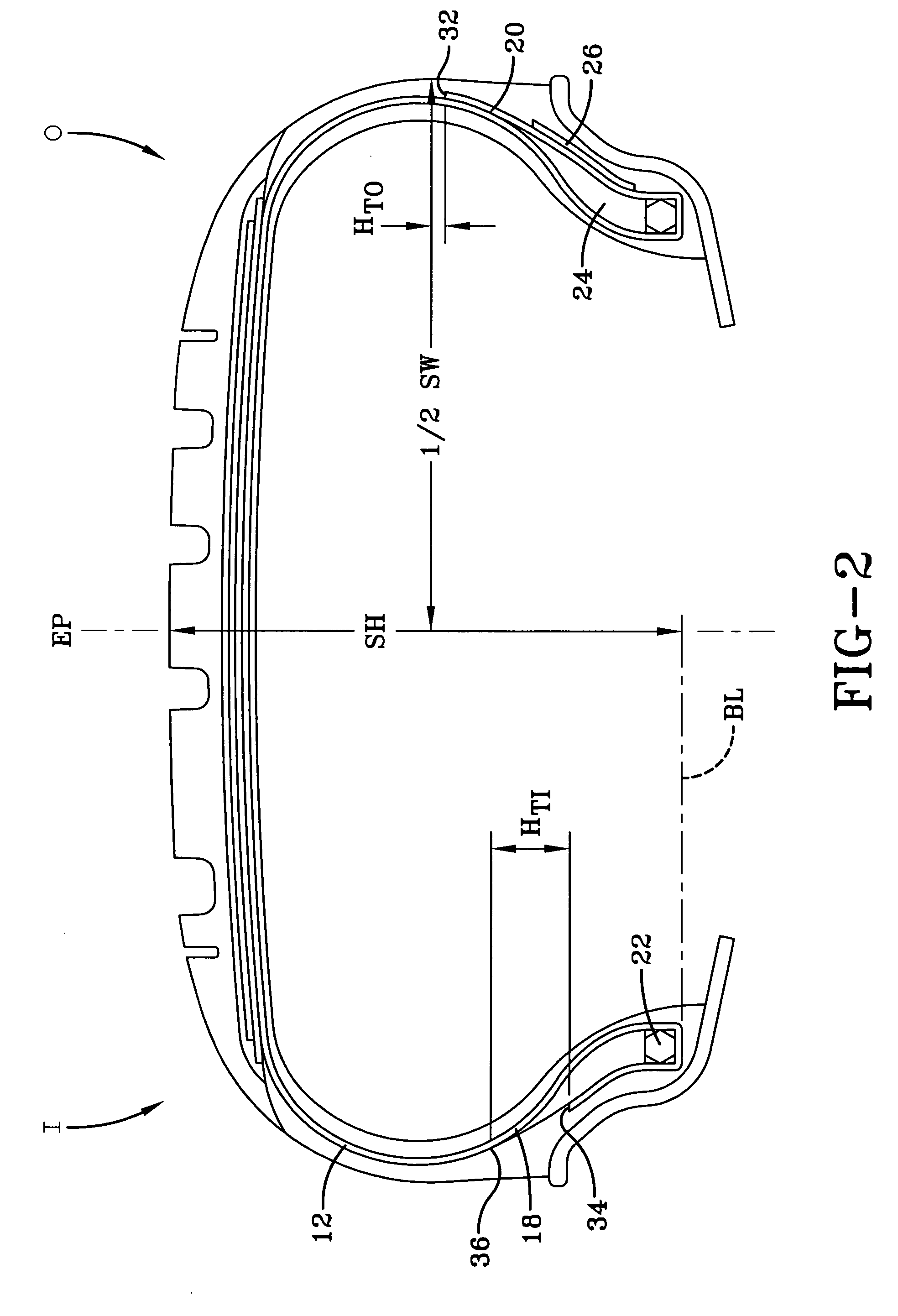
[0035]FIG. 1 illustrates a pneumatic tire in accordance with the present invention. The pneumatic tire is a low aspect radial tire, preferably designed for use as a high performance tire. The pneumatic tire has a carcass, a belt structure 8 radially outward of the carcass, and a tread 10 radially outward of the belt structure 8. The belt structure 8 may be any of the type conventionally used for a passenger vehicle tire, and generally will include two reinforcement plies of cords with overlay plies covering at least the axially outer edges of the individual belt reinforcement plies.

[0036] The carcass has at least one carcass reinforcing ply 12, a pai...


PUM


Abstract

A pneumatic radial tire has a carcass and a tread. The carcass has at least one carcass reinforcing ply and opposing bead portions. Each bead portion has a bead core and a bead apex radially. The apexes in each bead portion having the same radial height (HA), as measured from a bead base line (B). The tire has a bead reinforcing ply comprising carbon fiber reinforcing cords located in only one bead portion of the tire, with the bead reinforcing ply being adjacent to the carcass reinforcing ply.

Description

FIELD OF THE INVENTION [0001] The present invention is directed towards a pneumatic tire. More specifically, the present invention is directed towards a pneumatic tire with asymmetrical reinforcement in the lower sidewalls and bead regions of the tire to enhance high performance aspects of the tire. BACKGROUND OF THE INVENTION [0002] Pneumatic tires are conventionally constructed to have a symmetrical internal construction; the symmetric being centered on the lateral center, or equatorial plane, of the tire. Laboratory studies have shown that a majority of a tire's net cornering force is generated in the area of the shoulder on the inside of the direction of turn. Roll and lateral deflection to the outside tend to lift this inside shoulder, reducing the tire's cornering capability. In many vehicles, the vehicle's suspension system compensates for the reduced cornering capability by cambering of the vehicle wheels. In cambering, the top of a wheel and tire are tilted toward the cente...

Claims


Application Information

Patent Timeline
Patent Type & Authority Applications(United States)
IPC IPC(8): B60C15/00
CPCB60C15/06B60C11/0304Y10T152/10864Y10T152/10504Y10T152/10819B60C2015/0639
Inventor POLING, DAVID CHARLESWESTGATE, WALTER KEVINPUHALA, AARON SCOTTMARAZZI, ERIC JOHNWEBER, MICHAEL JOSEPHGSCHNELL, CRISTINA MARIEMORRISON, ANDREW EDWARDSCHMALIX, CHARLES KENNETHBARNETTE, RACHEL REBEKAHSANDSTROM, PAUL HARRY
Owner POLING DAVID CHARLES
Why Eureka
Try Eureka