Heat exchanger and air conditioner

a technology of heat exchanger and air conditioner, which is applied in the field of air conditioner, can solve the problems of increasing the temperature increasing the pressure loss of air flow, and increasing the variation of air blown into the vehicle compartment. it can avoid the increase of the pressure loss of air flow, and enhance the degree of mixing of cold air

Inactive Publication Date: 2007-06-07
DENSO CORP
View PDF15 Cites 15 Cited by
  • Summary
  • Abstract
  • Description
  • Claims
  • Application Information

AI Technical Summary

Benefits of technology

[0009] In view of the above-described problems, an object of the present invention is to avoid an increase in a pressure loss of an air flow and to enhance the degree of mixing of cold air and hot air in an air conditioner.

Problems solved by technology

As a result, when a distance L1 from the heating heat exchanger 24 to the air blowoff openings (face opening parts 35a, 35b) is short, cold air and hot air are blown into the vehicle compartment before they are not sufficiently mixed with each other, thereby causing a problem that variations in the temperature of air blown into the vehicle compartment are large.
However, in this case, the installation of the air guide will increase a pressure loss of the air flow.
However, even in U.S. Pat. No. 5,062,473, when the above-described distance L1 is short, the cold air is not sufficiently mixed with the hot air, which results in increasing variations in the temperature of air blown into the vehicle compartment.

Method used


Image

  • Heat exchanger and air conditioner
  • Heat exchanger and air conditioner
  • Heat exchanger and air conditioner

Examples


first embodiment

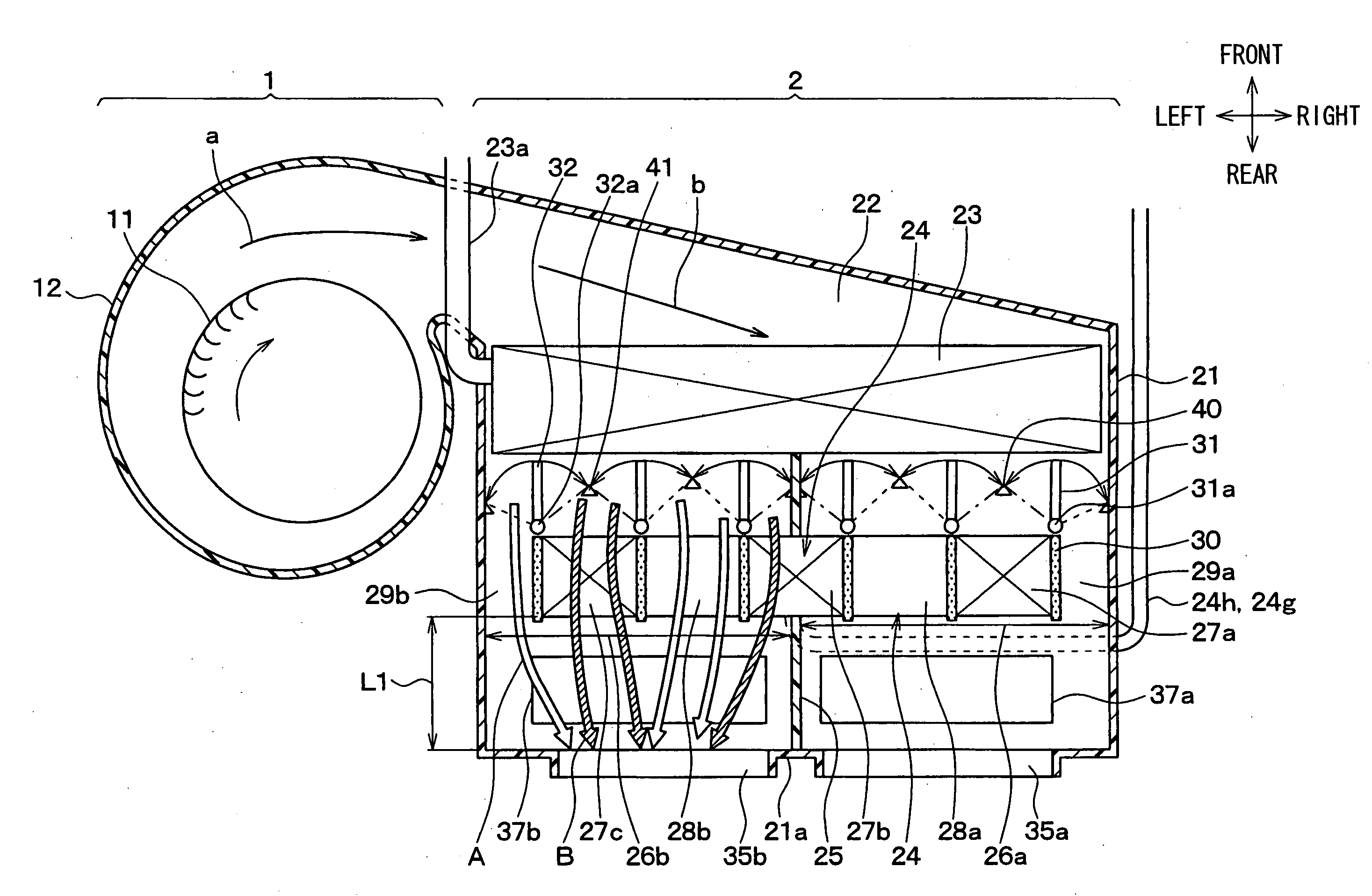
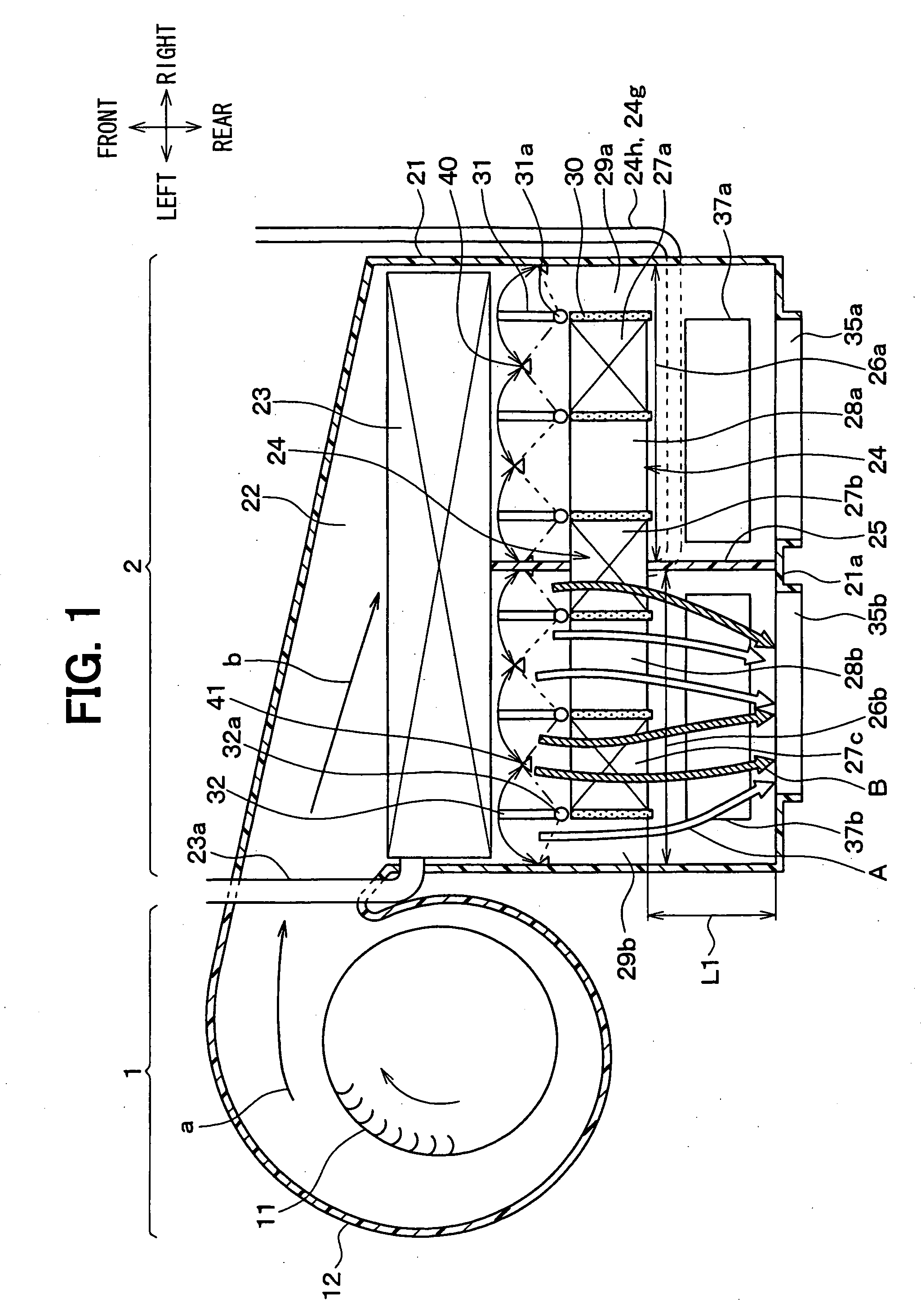
[0034] As shown in FIG. 1, an interior unit of an air conditioner for a vehicle is located in a vehicle compartment, and is broadly divided into tow parts of a blower unit 1 and an air conditioning unit 2 in this embodiment. The air conditioning unit 2 is located nearly in a center area in the right and left direction of the vehicle inside an instrument panel (dashboard) on the front of the vehicle compartment.

[0035] In contrast to this, the blower unit 1 is arranged offset to a position on the front of a front passenger's seat, that is, to a side of the air conditioning unit 2 in the right and left direction of the vehicle. Here, this embodiment, the air conditioner is typically used for a car with a right-hand steering wheel in which a front passenger's seat is located on the left side of the vehicle.

[0036] The blower unit 1 has a well-known construction including a blower fan 11 made of a centrifugal fan having many blades arranged in the shape of a circular ring, a motor (not ...

second embodiment

[0096]FIG. 6 shows a second embodiment of the present invention. In the second embodiment, the cold air bypass passage 28a of the heater core 24 is formed at only one position in the center area in the direction of the length of the tank, and the heating parts 27a, 27c are formed on both the right and left sides of the cold air bypass passage 28a. The second embodiment is the same in the other points as the first embodiment, so the same parts are denoted by the same reference symbols and their descriptions will be omitted.

[0097] In the second embodiment, at four positions, the cold air is mixed with the hot air and the number of positions at which the cold air is mixed with the hot air is decreased as compared with the first embodiment. However, as compared with the comparative example shown in FIG. 15, the number of positions at which the cold air is mixed with the hot air is doubled, so the degree of mixing of the cold air and the hot air can be enhanced.

[0098] As described in t...

third embodiment

[0099]FIG. 7 shows a third embodiment in which the cold air bypass passage 28a and the heating parts 27a, 27c of the heater core 24 are arranged in the up and down direction. That is, one cold air bypass passage 28a is arranged in the middle (center) in the up and down direction of the heater core 24 and the heating parts 27a, 27c are arranged on both up and down sides of the cold air bypass passage 28a.

[0100] The cold air bypass passage 29a arranged outside of the heater core 24 is formed on the upper side of the upper heating part 27a.

[0101] There are provided three air mixing doors 31 rotated in the up and down direction in association with each other. When these three mixing doors 31 are rotated, the one cold air bypass passage 28a, the two heating parts 27a, 27c, and the one cold air bypass passage 29a arranged outside of the heater core 24 are opened or closed.

[0102] Also in the third embodiment, there are formed three positions where the cold air is mixed with the hot air,...


PUM


Abstract

A heating heat exchanger includes plural tubes which are arranged in parallel and through which a thermal fluid for heating air flows, and plural fins which are joined to the tubes. The tubes and the fins are arranged to form plural heating parts equal to or more than three in which air is heated, and at least two bypass passages each of which is provided between adjacent heating parts, through which the air passes without exchanging heat with the thermal fluid. Furthermore, first and second tank parts for distributing the thermal fluid to and for collecting the thermal fluid from the tubes are arranged at two longitudinal ends of the tubes and extend to across an area where the bypass passages and the heating parts are provided. In addition, the bypass passages and the heating parts are arranged in an arrangement direction perpendicular to an air flow direction.

Description

CROSS REFERENCE TO RELATED APPLICATION [0001] This application is based on Japanese Patent Applications No. 2005-351888 filed on Dec. 6, 2005, and No. 2006-111823 filed on Apr. 14, 2006, the contents of which are incorporated herein by reference in its entirety. FIELD OF THE INVENTION [0002] The present invention relates to an air conditioner that adjusts the ratio between cold air and hot air to adjust the temperature of air blown into a room, and a heat exchanger used for an air conditioner. BACKGROUND OF THE INVENTION [0003] Conventionally, an air-mixing type air conditioner, which adjusts the ratio between cold air and hot air to adjust the temperature of air blown into a room, is a typical air conditioner for a vehicle. FIG. 15 shows a conventional structure of this air-mixing type air conditioner and shows a right-and-left independent control type air conditioner in which an air passage in a case 21 is partitioned into a right air passage 26a and a left air passage 26b by a pa...

Claims


Application Information

Patent Timeline
Patent Type & Authority Applications(United States)
IPC IPC(8): F28F27/00F28F27/02G05D23/00
CPCB60H1/00028B60H1/00328B60H2001/00164F28D1/05366F28D2001/028F28F27/02F28F2250/06F28F2270/00
Inventor ITOU, KOUJI
Owner DENSO CORP
Why Eureka
Try Eureka