Aerodynamic drag reducing apparatus

a technology of aerodynamic drag reduction and airflow separation, which is applied in the direction of roofs, transportation and packaging, vehicle arrangements, etc., can solve the problems of substantial increase in vehicle length, impracticality on crowded urban roadways, in parking lots, in campgrounds, etc., and achieves the effect of reducing fuel consumption, reducing energy consumption, and reducing airflow separation and aerodynamic drag

Active Publication Date: 2007-06-07
STEMCO PROD INC
View PDF62 Cites 64 Cited by
  • Summary
  • Abstract
  • Description
  • Claims
  • Application Information

AI Technical Summary

Benefits of technology

[0008] The present invention is concerned with providing an aerodynamic drag reducing apparatus for vehicles with the purpose of reducing energy consumption. More specifically, this is achieved by adding gently sloping surfaces downstream of rear facing surfaces of the vehicle with the goal of reducing airflow separation and aerodynamic drag. This, in turn, reduces fuel consumption.
[0009] On certain vehicles, simply adding the required additional surfaces would result in a substantial increase to the vehicle length. This length would be acceptable, in many cases, on the open road in uncongested traffic, but would be impractical on crowded urban roadways, in parking lots, in campgrounds, and by loading docks. To address this, the present invention has two primary configurations. The first is an extended configuration that reduces drag and fuel consumption, especially at highway speeds. The second is a retracted configuration that provides much less, if any, drag reduction, but results in a more compact vehicle that is practical in crowded areas. This combination of configurations in the same apparatus is especially useful since zones of higher speed traffic are often not congested. These high-speed zones are also where the drag reducing potential is the highest. Likewise, congested areas often have reduced traffic speed with less drag reducing potential, but in these cases, the retracted configuration may be required for maneuvering.
[0010] In order to easily and conveniently convert between the retracted configuration and the extended configuration, the present invention employs panels that fold as part of an apparatus attached to the rear of the vehicle.

Problems solved by technology

On certain vehicles, simply adding the required additional surfaces would result in a substantial increase to the vehicle length.
This length would be acceptable, in many cases, on the open road in uncongested traffic, but would be impractical on crowded urban roadways, in parking lots, in campgrounds, and by loading docks.

Method used


Image

  • Aerodynamic drag reducing apparatus
  • Aerodynamic drag reducing apparatus
  • Aerodynamic drag reducing apparatus

Examples


first embodiment

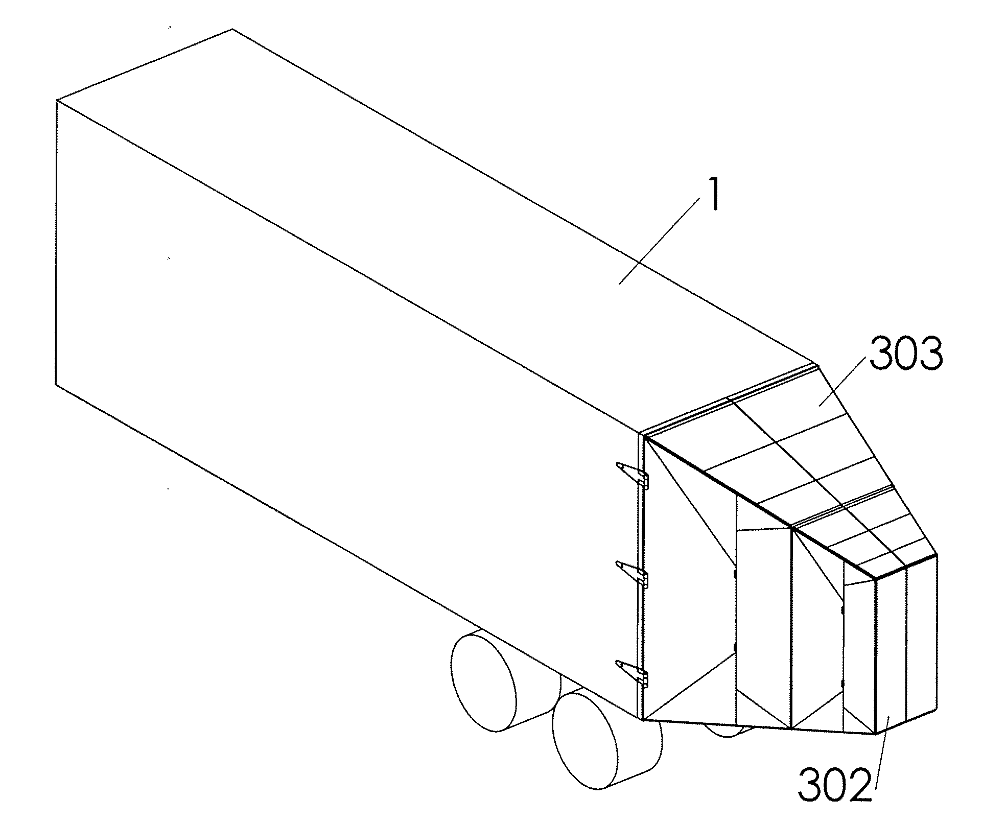
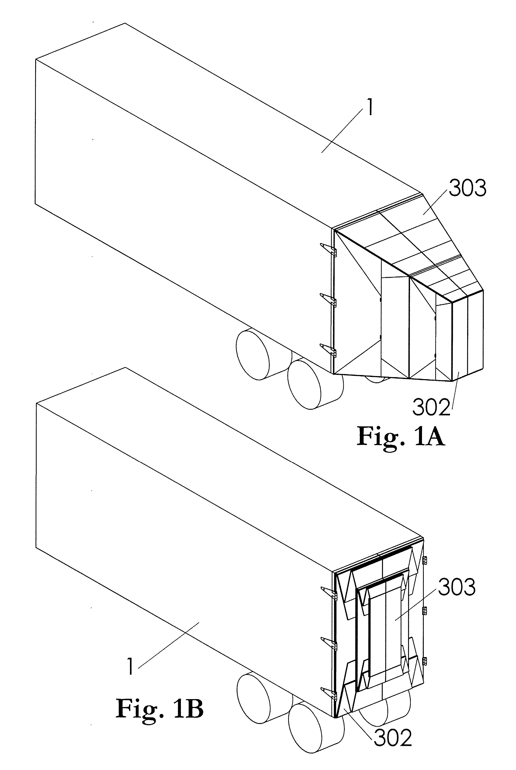
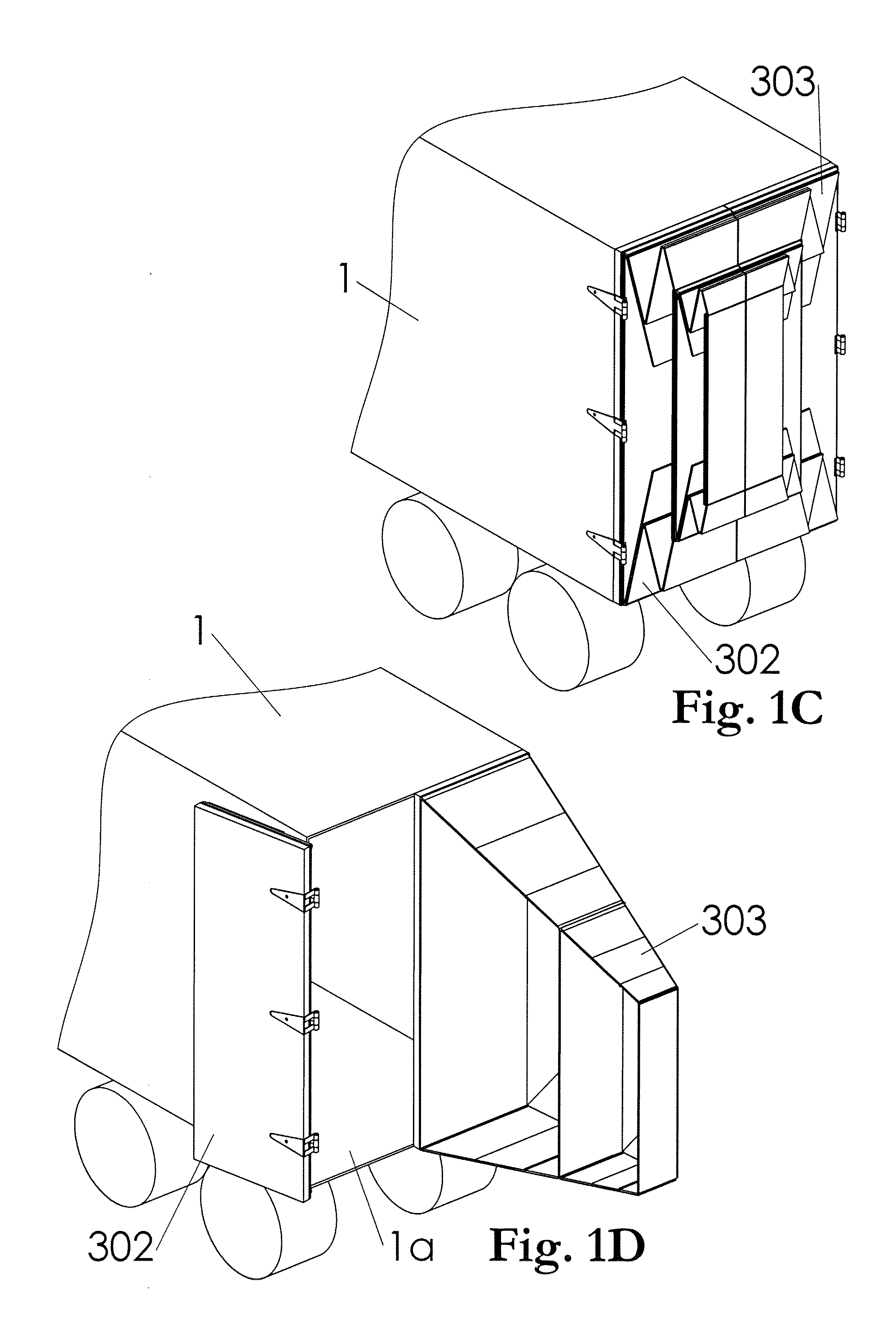
[0138] Referring now to the figures, in particular to FIGS. 1A through 1M, there is shown the present invention mounted on the rear of an exemplary over-the-road trailer 1. More specifically, a left hand apparatus 302 and a right hand apparatus 303 are mounted and shown in various configurations. FIGS. 2A through 2D show the right hand apparatus 303 in detail and in various configurations. In the present embodiment, the right rear trailer door serves as a mounting platform for the right hand apparatus 303 and may also be integrated to become part of the apparatus 303. The exterior shape of the left hand apparatus 302 is a mirror image of the right hand apparatus 303. The same relationships between the left hand door and the left hand apparatus 302 exist as mentioned above for the right. To gain access to the cargo holding area 1A of the trailer 1, the apparatuses 302 and 303 are opened as typical trailer doors or with the trailer doors.

[0139] If the apparatuses 302 and 303 are symme...

second embodiment

[0150] The discussions above focus primarily on an embodiment of the present invention suited for vehicles with rear doors having vertical hinge-lines served by two apparatuses 302 and 303. Vehicles and trailers with neither rear doors nor need for access to the rear of the vehicle are better served by the present invention that spans the width of the vehicle. This embodiment is formed by combining the two apparatuses 302 and 303, at their common edges, into a single apparatus, as illustrated by the panel group 411 in FIGS. 10A through 10C. More specifically, the right hand and left hand versions of the panel group 311 are combined by joining the common edges of the front, rear, top, and bottom panels 320, 321, 325, 326, 330, 331, 332, and 333. As in the previous embodiment, multiple panel groups can be arranged one behind the other to form an extended apparatus. As in the preceding panel groups 311 and 312, the configuration of the combined panel group 411 is also controlled by a s...

third embodiment

[0152] the present invention is arrived at by splitting the apparatus in the preceding paragraph, exemplified by panel group 411, about a horizontal plane near its center, creating two halves: one upper apparatus and one lower apparatus. This embodiment is illustrated by the panel groups 511 and 611 shown in FIGS. 11, 12A through 12C, and 13A through 13C. This configuration is suited for use on vehicle doors with horizontal hinges. This embodiment could also be rotated ninety degrees and used on vehicles whose doors have vertical hinges. As in the previous embodiments, panel groups in successively smaller sizes can be connected one behind the other to extend the gently sloping surfaces and reduce the rear-facing area in the fully extended configuration. This embodiment retains the desirable characteristics of stability and configuration by a single variable. Panel groups of this embodiment can be used individually. For example, the panel group 611 in FIGS. 13A through 13C could be u...


PUM


Abstract

An aerodynamic drag reducing apparatus for use with vehicles having downstream surfaces that are not streamlined. The apparatus consists of folding panels that extend rearward for use in a drag reducing configuration and collapse for use in a space saving configuration.

Description

CROSS REFERENCE TO RELATED APPLICATION [0001] This application claims the benefit of U.S. Provisional Patent Application Ser. No. 60 / 741,155, filed Dec. 1, 2005, which application is hereby incorporated by reference in its entirety.TECHNICAL FIELD [0002] The present invention relates to an aerodynamic drag reducing apparatus for use with vehicles having downstream surfaces that are not streamlined. Examples include: over-the-road trucks and truck trailers, vans and minivans, motor homes and travel trailers, and pickup trucks. In vehicles such as pickup trucks, one non-streamlined surface is near the center of the vehicle. The present invention is suitable for use with vehicles having rear doors. BACKGROUND [0003] It is known that a significant amount of aerodynamic drag is created when a vehicle travels at velocities typical on a modern roadway. This is due, in large part, to areas of low pressure that are induced on the rear surfaces of the vehicle. The low pressure becomes more pr...

Claims


Application Information

Patent Timeline
Patent Type & Authority Applications(United States)
IPC IPC(8): B60R27/00B60N3/00B60R99/00
CPCB62D35/001
Inventor BREIDENBACH, THOMAS SCOTT
Owner STEMCO PROD INC
Why Eureka
Try Eureka