Technique for accurate estimate of large antenna inertial two dimensional orientation using relative GPS spatial phase

a technology of spatial phase and antenna position, applied in the direction of antennas, instruments, measurement devices, etc., can solve the problems of insufficient accuracy of the angle dependent on mechanical gears having backlash, insufficient to determine the orientation of the antenna in typical radar applications, and insufficient position accuracy to be used for antenna orientation purposes

Active Publication Date: 2007-06-07
RAYTHEON CO
View PDF5 Cites 25 Cited by
  • Summary
  • Abstract
  • Description
  • Claims
  • Application Information

AI Technical Summary

Problems solved by technology

Such an approach dependent on mechanical gears having backlash is insufficiently accurate where a SAR display depends on antenna angle orientation, especially where the SAR map has resolution of a few feet at a range of 50 nautical miles.
This accuracy is sufficient for determining the general location of an antenna but insufficient to determine ante

Method used


Image

  • Technique for accurate estimate of large antenna inertial two dimensional orientation using relative GPS spatial phase
  • Technique for accurate estimate of large antenna inertial two dimensional orientation using relative GPS spatial phase
  • Technique for accurate estimate of large antenna inertial two dimensional orientation using relative GPS spatial phase

Examples


Embodiment Construction

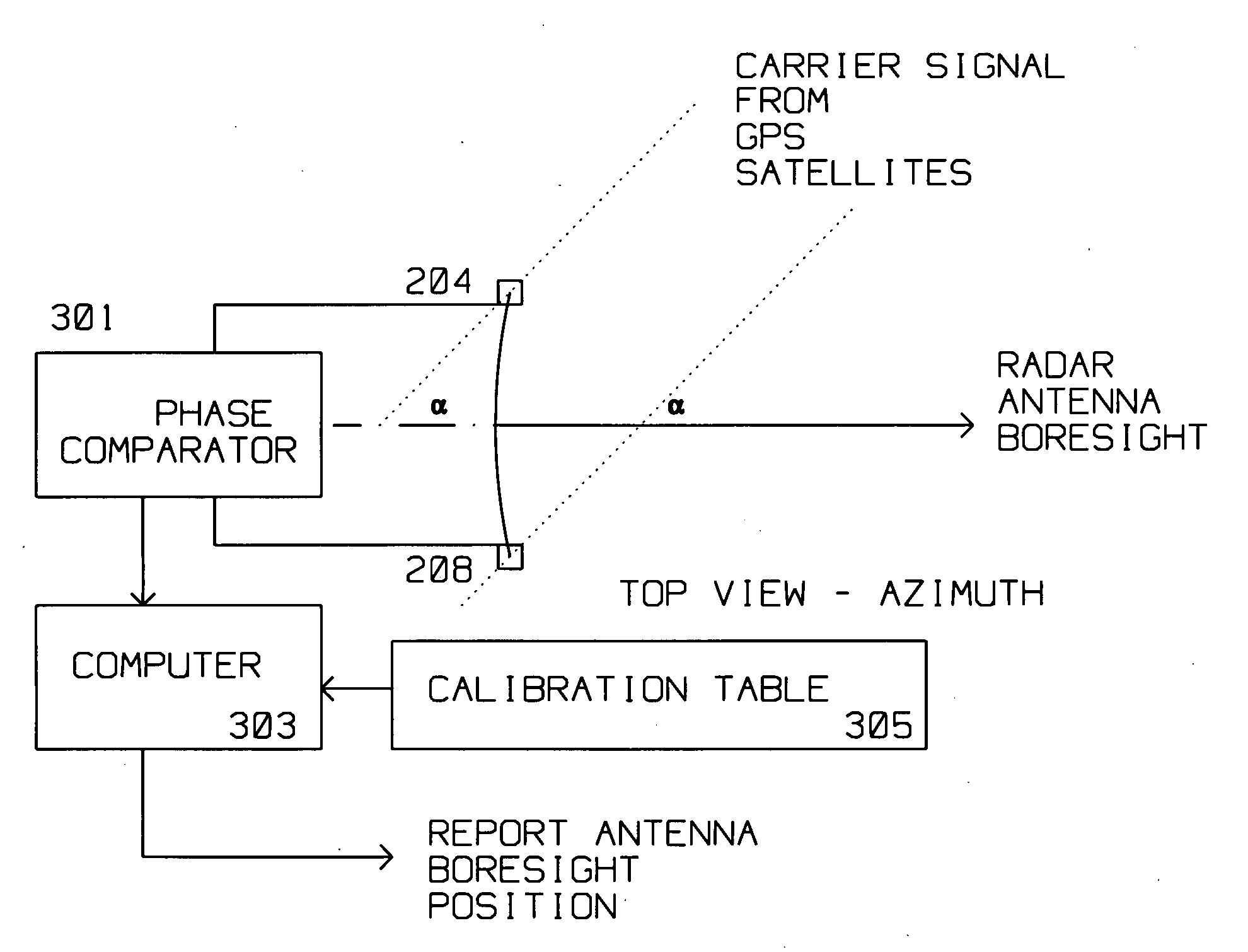
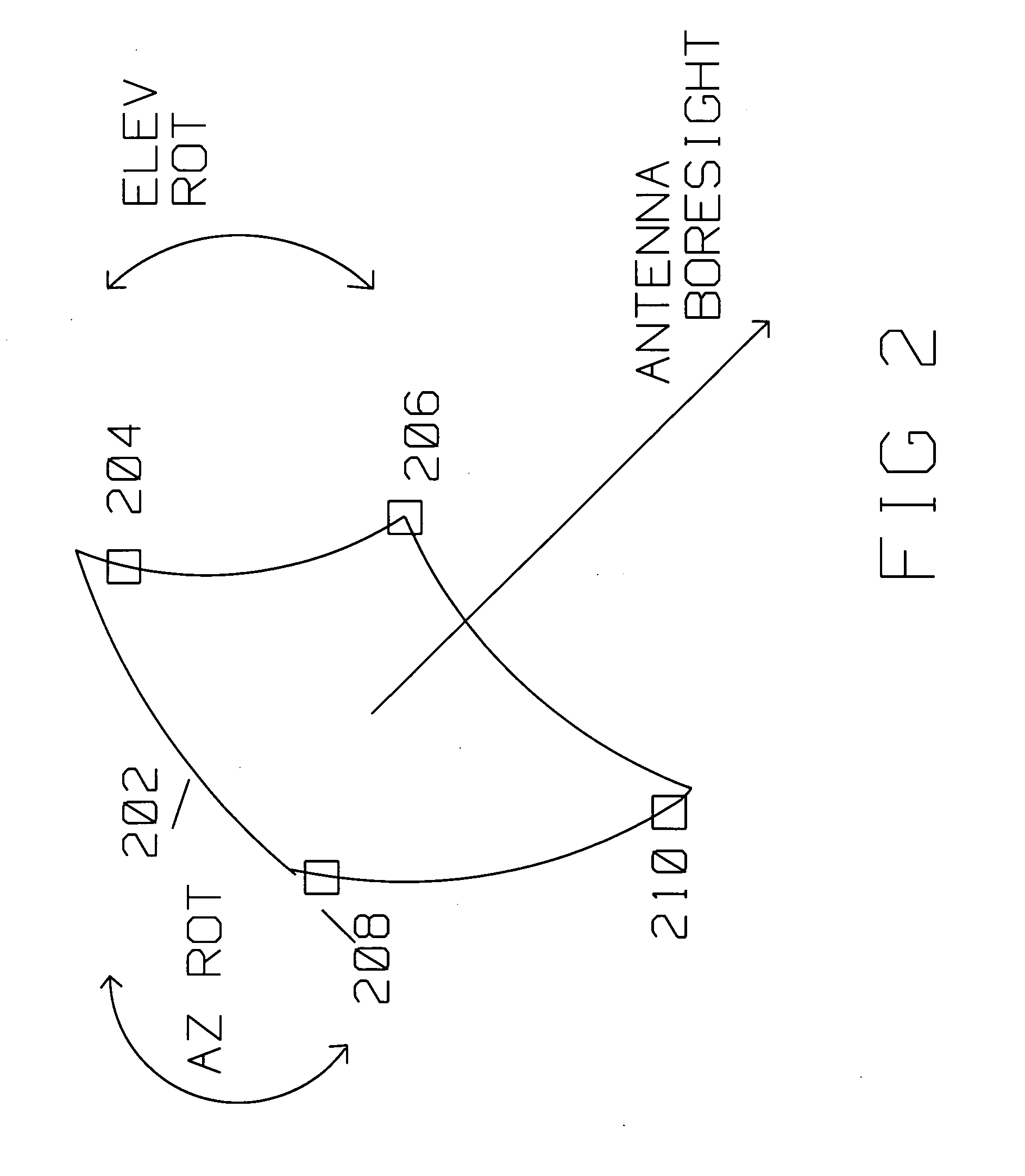
[0017] The present disclosure describes a method and apparatus for collecting antenna position measurements using phase measurements from a plurality of GPS sensors mechanically connected to structurally stiff locations on a large radar antenna, and combining the plurality of target motion measurements to improve overall antenna orientation accuracy as compared to previous approaches.

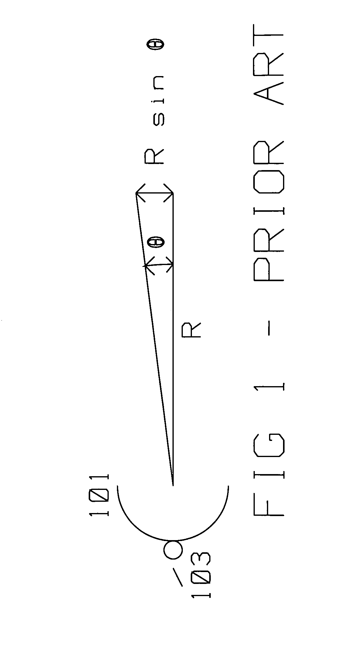
[0018]FIG. 1 shows an antenna 101 of the prior art where the azimuth orientation of the antenna is measured by a rotating angle transducer 103 capable of reporting the antenna azimuth angle position. From geometric considerations, if the uncertainty, or error of the reported azimuth angle from transducer 103 is θ, then the azimuth error at range R is:

Azimuth Error=R sin θ

[0019] For example, for R=50 nautical miles (nm), and θ=10 milliradians, (about ½ degree) the resulting azimuth error is approximately:

50 nm·6076.1 ft / nm·0.01 radians =3038 ft

[0020] Thus, mechanical angle transducers having an accuracy...


PUM


Abstract

A radar antenna has a reflector and maximum gain along its boresight. The reflector has a periphery, typically circular, rectangular or elliptical. A plurality of Global Positioning System (GPS) satellite signal receiving antennas are rigidly, mechanically attached to the reflector near its periphery. The plurality of GPS satellite signal receiving antennas are connected pairwise to a phase comparator for comparing a plurality of first phase differences induced by a first GPS satellite signal received concurrently between the plurality of GPS satellite signal receiving antennas. A Phase comparator measures the phase difference of the signal received at GPS satellite signal receiving antennas pairwise thus performing a differential phase measurement. This differential phase measurement is supplied to a computer for identifying an ambiguous boresight position using the phase differences measured by the phase comparator. The position of the GPS satellites is known with respect to the geo-location of the antenna. Thus, the boresight angle is derived from the phase difference of the carrier signal from the GPS satellite being received and the mechanical alignment information between the GPS satellite receiving antennas and radar antenna boresight stored during calibration/manufacture of the radar antenna. The ambiguity in the computed boresight position is resolved by making differential phase readings using the same GPS antennas from a second GPS satellite signal supplied by a second satellite.

Description

BACKGROUND OF THE INVENTION [0001] 1. Field of Invention [0002] This invention is in the field of antenna position location using signals from a satellite constellation part of the Global Positioning System (GPS). [0003] 2. Description of the Related Art [0004] Synthetic Aperture Radar (SAR) is used for ground mapping as well as target identification. The general principle behind SAR is to coherently combine the amplitude and phase information of radar returns from a plurality of sequentially transmitted pulses. These pulses are from a relatively small antenna on a moving platform. As the platform moves, the information contained in the pulses is coherently combined to arrive at a high resolution SAR image. [0005] The plurality of returns creating a SAR image generated by the transmitted pulses along a presumed known path of the platform make up an array. Theoretically, during the array, amplitude as well as phase information returned from each of the pulses, for each of many range ...

Claims


Application Information

Patent Timeline
IPC IPC(8): G01S5/02H01Q3/00G01S19/54G01S5/14
CPCG01S19/54H01Q19/132
Inventor KRIKORIAN, KAPRIEL V.ROSEN, ROBERT A.
Owner RAYTHEON CO
Why Eureka
Try Eureka