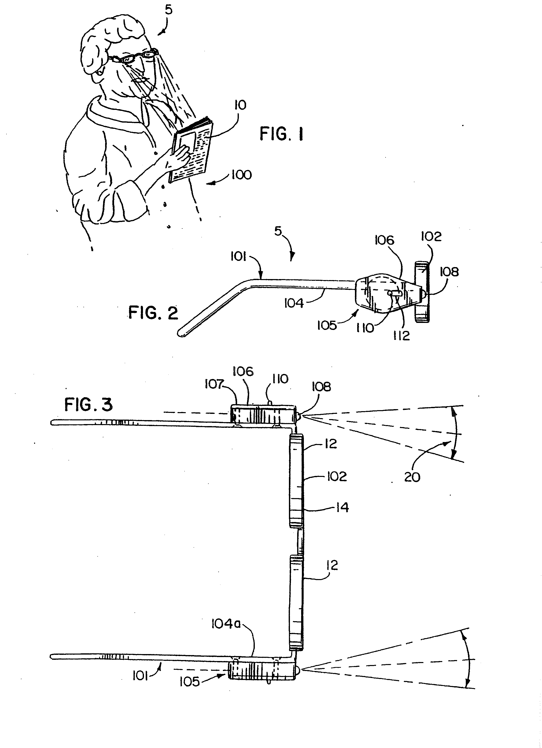
[0010] In accordance with one form of the invention, lighted glasses, and preferably those adapted for reading which include corrective lenses, e.g. magnifiers, are provided to enable conventional sized text to be clearly read in dimly lit areas when held at a
normal range of reading distances at which a user typically reads such material, such as between ten inches and eighteen inches from the lenses. High strength lights and light mounts therefor cooperate to light the reading area with a maximum amount of light provided in the
reading distance range. More particularly, highly efficient and
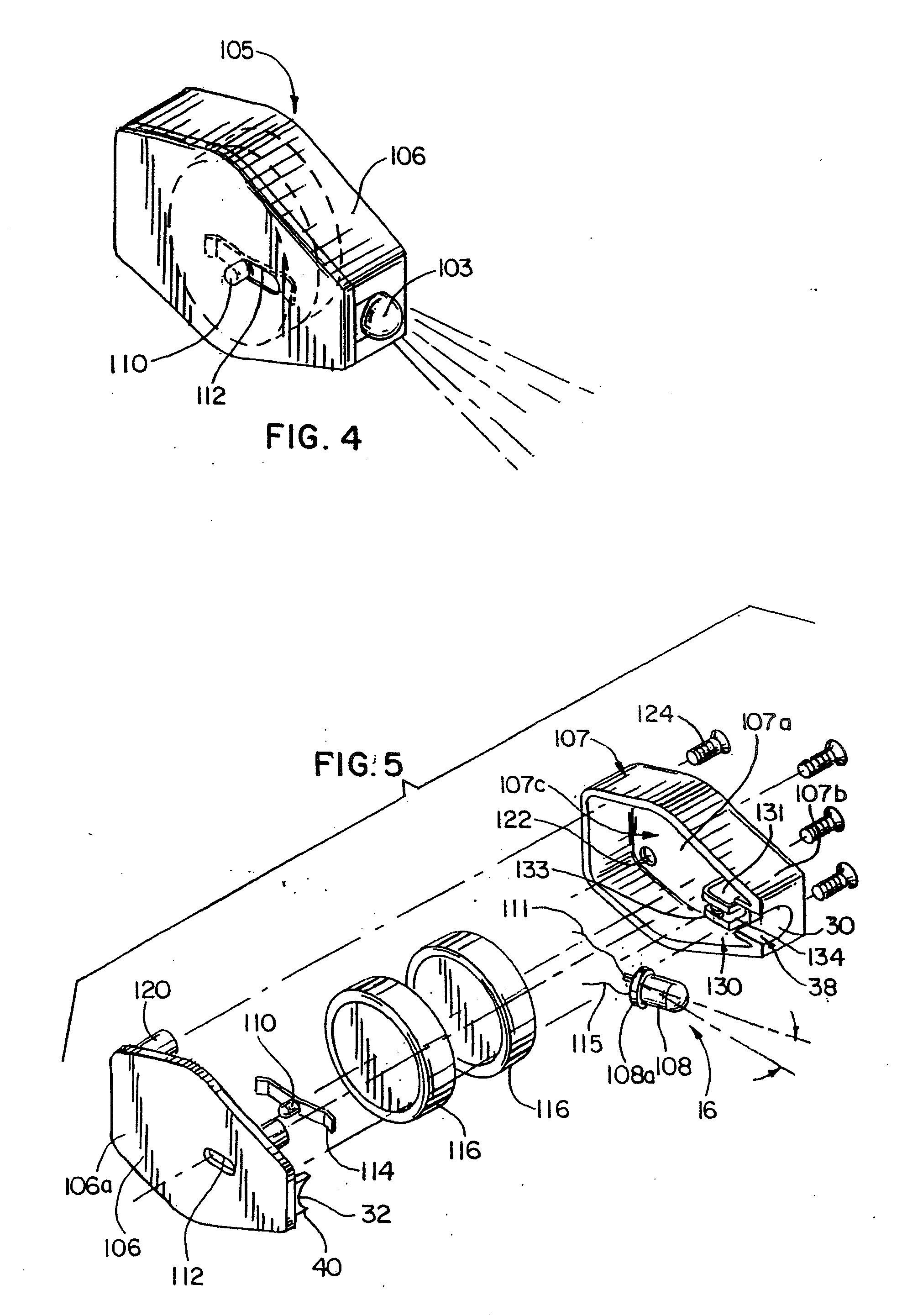
high intensity light emitting diodes (LEDs) are mounted in housings configured to fix narrow beams of light to be directed slightly inward toward each other so that the beams overlap in the
reading distance range thus providing double the amount of light for reading over that provided by a single one of the lights. To this end, the housings are attached adjacent outer portions of the lenses so that the inwardly directed light beams light up the areas generally in front of the glasses, i.e. in its
field of view, and which begins spaced forwardly therefrom, i.e. generally coinciding with the start of the reading distance range. Further, the small size and efficient nature of the preferred
solid-state material, i.e. InGaN (
indium gallium nitride), for the LEDs, allows very small power supplies to be used such as disc-shaped
coin cell batteries for powering the LEDs which, in turn, allows both the light source and power source herein to be self-contained in a highly compact housing therefor. In this regard, the present invention also contemplates the provision of compactly sized lighting modules as described above that can be attached to reading or other glasses either removably or fixed in a more permanent fashion as described hereinafter, or to other items typically worn as headgear such as hats or the like.
[0011] The beams of light from the LEDs generate conical-shaped lighted areas such that upon intersection they cooperate to form a conical overlapping lighted area in which the brightness of the light is effectively doubled over that provided by a single LED. The conical overlapping lighted area increases in size as distances increase from the lenses. As is known, light tends to dissipate the further it is from its source. The overlapping conical lighted area is such that the
peripheral areas in the
field of view of the lenses that do not receive the double light strength of the overlapping light beams are closest to the lenses where light dissipation has its least effect in the reading distance range, whereas the overlapping lighted area increases in size further from the lenses with a corresponding decrease in the single light strength
peripheral areas on either side of the cone of overlapping light. Thus, as light dissipates and distances increase from the lenses, the lighting provided will not suffer as the double light strength of the overlapping conical region of light will more than make up for the effects of light dissipation in the reading distance range.
[0014] The preferred LEDs herein are a small lightweight device that provides a very
bright light, while consuming very little power. As such, the batteries enclosed in the housing are small and do not need to be changed as frequently as devices that utilize incandescent lights or fiber
optics, which require large batteries. The LEDs provide a relatively
narrow beam of light that can be well focused in a particular direction. For example, if two light modules are mounted on a pair of glasses, the LEDs in each module are positioned such that the cones of light produced by the LEDs in the light modules begin intersecting at a point closely adjacent to or coinciding with the start of the range of ideal reading distances. As such, the illuminated reading portion receives the brightest light possible since the intersection of both cones of light are trained on that area. Another
advantage of using the
high intensity LEDs is that because they consume such a small amount of power, virtually no heat is dissipated. Therefore, a user is able to wear eyeglasses having the light modules mounted thereon, for longer periods of time without suffering from heat and without being bothered by the weight of the devices.
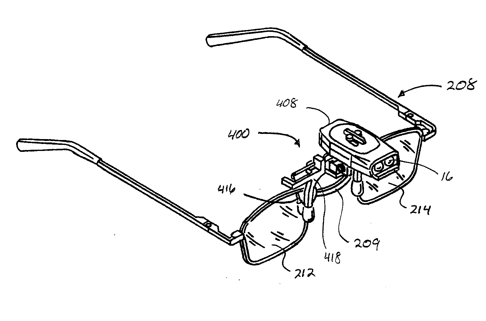
[0017] In another embodiment, a compact clip-on light apparatus is provided including a light module, a clipping mechanism, and a polyaxial
coupling joint between the light module and the clipping mechanism. The polyaxial coupling joint permits the light module to be pivoted about a plurality of axes for directing light in a desired direction. The polyaxial coupling joint provides advantages over prior art lighted glasses or prior clip-on light devices that only permit pivoting of the light source along a single pivot axes. The polyaxial coupling joint, on the other hand, permits light from the light module to be directed in a plurality of directions without necessitating that the item to which the light module is attached be adjusted or shifted. Preferably, the polyaxial coupling joint is configured so that the light module is pivotally rotatable about one pivot axis to provide even greater freedom of light positioning. The clip-on light apparatus with the polyaxial coupling joint, therefore, is more versatile than prior clip-on lighting devices, especially when coupled to eyeglasses or headgear, because the direction of the light can be changed by pivoting or rotating the light in one of a variety of directions relative to the frame instead of the user needing to turn their head or reposition the device.
[0018] In a preferred form, the clip-on light apparatus includes a retention device that is arranged and configured to
restrict movement of the light module about a pivot axis at the polyaxial coupling joint. Most preferably, the pivot axis for which the retention device is operable is a variable pivot axis that itself is pivotal in a plane with the module pivoted laterally to either side of the plane. The retention device is operable to generate a holding force at the coupling joint so that the amount of pivoting of the light module about the pivot plane can be controlled. Depending on whether the retention device is loosened or tightened, more or less pivoting of the light module about the pivot plane can occur. The resistance to pivoting about the pivot plane via the retention device can generate minimal play within the polyaxial coupling joint about the pivot plane. For example, tightening the retention device provides increased holding forces on the polyaxial coupling joint resulting in more resistance to pivoting of the light module laterally about the pivot plane. Conversely, loosening the retention device permits greater freedom of movement in the polyaxial coupling joint due to lower holding forces directed on the polyaxial coupling joint.


