Computer-vision system for classification and spatial localization of bounded 3d-objects

object technology, applied in the field of object recognition in a computer vision system, can solve the problems of system unacceptably low processing speed, high price of fixings, and serious drawbacks of computer vision systems developed so far

Active Publication Date: 2007-06-07
SCAPE
View PDF18 Cites 68 Cited by
  • Summary
  • Abstract
  • Description
  • Claims
  • Application Information

AI Technical Summary

Benefits of technology

[0024] The invention may furthermore comprise the step of eliminating potential seed points identified near already defined contours. This is done preferably in order to avoid generation of contours that are too close to already existing contours.
[0060] The determination of the roll, tilt and pan are preferably only done for features having similar or identical intrinsic properties compared to the intrinsic properties in the database. In this way a lot of computing time may be saved.

Problems solved by technology

A bottleneck in the automation of production processes is the feeding of components and semi-manufactured articles to automatic systems for machining, assembly, painting, packing etc.
Fixtures are expensive, since the entire internal storage must be based on such fixtures.
The computer vision systems developed so far have serious drawbacks.
Some systems have unacceptably low processing speeds, others have poor generality.
The latter limitation is fundamental for the present systems, as the recognition model used does not include perspective effects in the 3D-2D transformation of the camera.
Thus, for parts higher than 5-10 cm, standard computer vision systems demand inconveniently remote cameras.
Furthermore, they are not able to guide robots to structured grasping randomly oriented parts piled in boxes and pallets.
Another bottleneck is present when recycled articles are to be classified as they arrive to the recycling plants.

Method used


Image

  • Computer-vision system for classification and spatial localization of bounded 3d-objects
  • Computer-vision system for classification and spatial localization of bounded 3d-objects
  • Computer-vision system for classification and spatial localization of bounded 3d-objects

Examples


Embodiment Construction

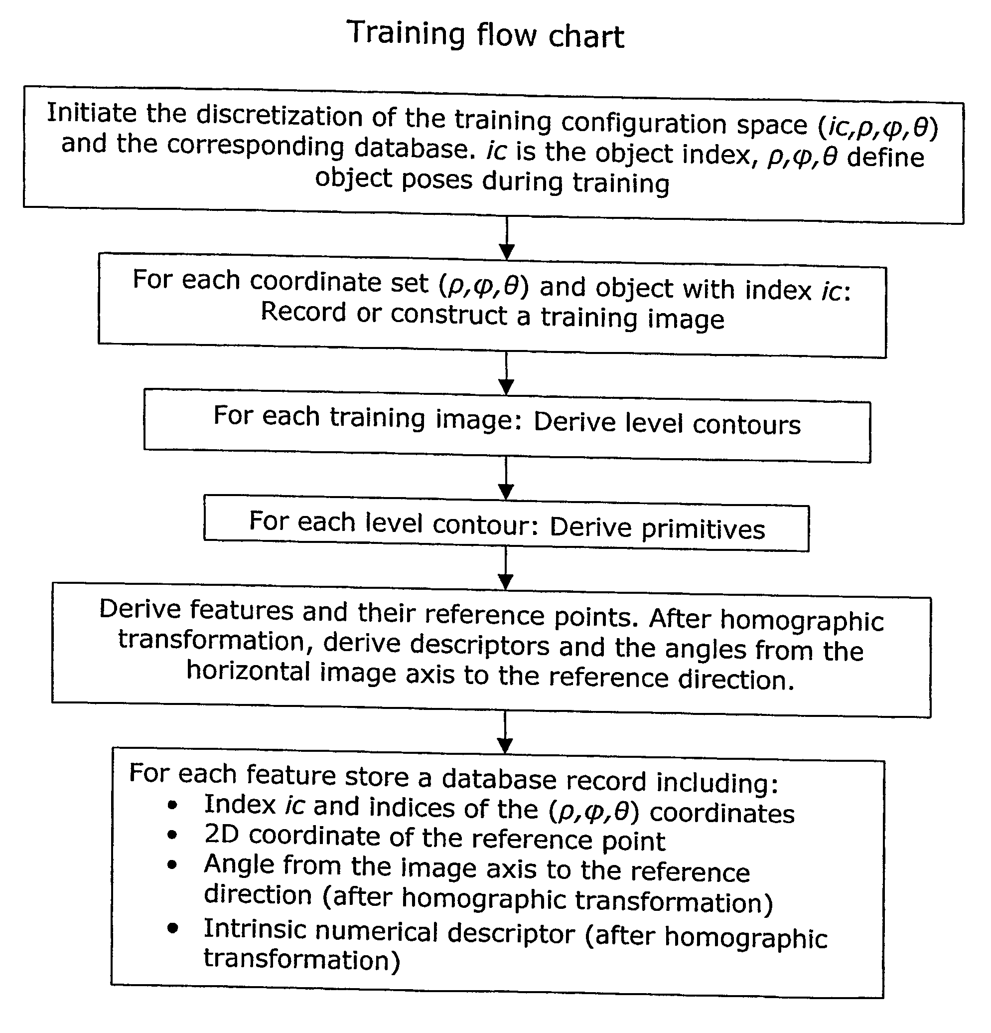
[0089] The invention described here is aimed at all the situations described in the section Background of the invention. Focus is put on the following properties: [0090] Simple generation of training information [0091] Reasonably low volume of training information. [0092] Exact treatment of the perspective effects [0093] Generality concerning the shape and the visual appearance of the objects, e.g. sharp 3D edges and landmarks are not necessary [0094] High speed recognition without extensive 2D matching between images or 3D reconstruction.

Functionality

[0095] The computer vision system is used for classifying and / or locating bounded 3D objects belonging to distinct classes. The system consists of one or more cameras whose images are interpreted in terms of 1) class of 3D objects and 2) their spatial position and orientation (pose). Its function is to some extent independent of possible partial occlusion by other objects and of poor image segmentation. The objects need not have cha...


PUM


Abstract

The invention relates to a system and method for recognition, classification and spatial localization of bounded 3D-objects. In particular it relates to a computerized method for recognition, classification and localization of objects. The method comprises generation of a training database based on a large number of training views recorded by a camera or constructed using a CAD representation of an object. Characteristic curves are derived from the training views, and primitives of the curves are detected. Intrinsic and extrinsic descriptors of features are stored in the database together with data about the object class and pose of the view. Finally the recognition takes place in two stages: First the intrinsic descriptors of the recognition view are compared with those of the database. Second, among the best matching features it is explored which features agree mutually in the sense that they suggest the same object class at the same pose.

Description

FIELD OF THE INVENTION [0001] The invention relates to a method for object recognition in a computer vision system, more specifically the method relates to classification and spatial localization of bounded 3D-objects. BACKGROUND OF THE INVENTION [0002] A bottleneck in the automation of production processes is the feeding of components and semi-manufactured articles to automatic systems for machining, assembly, painting, packing etc. Three main types of systems are available today: 1) vibration bowls, 2) fixtures, and 3) computer vision systems. Vibrating bowls are suitable only for components of small dimensions (less than about 5 cm). Fixtures are expensive, since the entire internal storage must be based on such fixtures. Both types of systems must be redesigned and remanufactured when new components are introduced. The computer vision systems developed so far have serious drawbacks. Some systems have unacceptably low processing speeds, others have poor generality. The fast and g...

Claims


Application Information

Patent Timeline
Patent Type & Authority Applications(United States)
IPC IPC(8): G06K9/00G06V10/46
CPCG06K9/48G06K9/6203G06T7/0042G06T7/0083G06T2207/30164G06T7/73G06T7/12G06V10/46G06V10/7515
Inventor BALSLEV, IVARERIKSEN, RENE DENCKE
Owner SCAPE
Why Eureka
Try Eureka