Temperature compensation for transmission between nodes coupled by a unidirectional fiber ring

a transmission node and temperature compensation technology, applied in the field of temperature compensation for transmissions, can solve the problems of inability to accept a synchronization solution, the gps synchronization may be less suitable for indoor systems, and the gps receiver is expensive, etc., and achieve the effect of accurate measuremen

Inactive Publication Date: 2007-06-07
OPTIS WIRELESS TECH LLC
View PDF24 Cites 28 Cited by
  • Summary
  • Abstract
  • Description
  • Claims
  • Application Information

AI Technical Summary

Problems solved by technology

But there are several drawbacks with topologies that rely on GPS-based synchronization.
First, GPS receivers are expensive.
Second, GPS synchronization may be less suitable for indoor systems since the GPS signal often cannot penetrate thick walls and cannot be used in tunnels, subways, and the like.
Third, some countries may not accept a synchronization solution based on GPS which allows the possibility of the mobile network being effectively disabled if some hostile entity gains control of the GPS system.
But absolute time synchronization is problematic with unidirectional fiber rings.
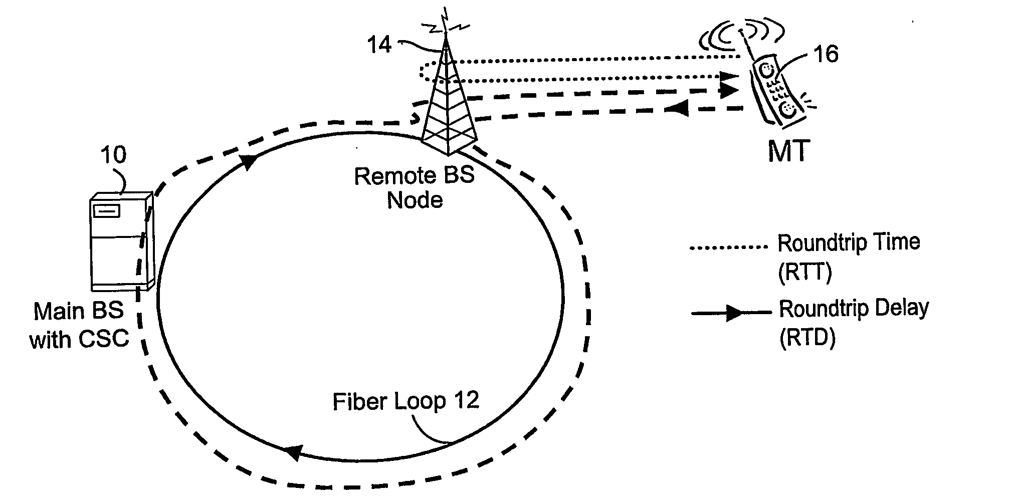
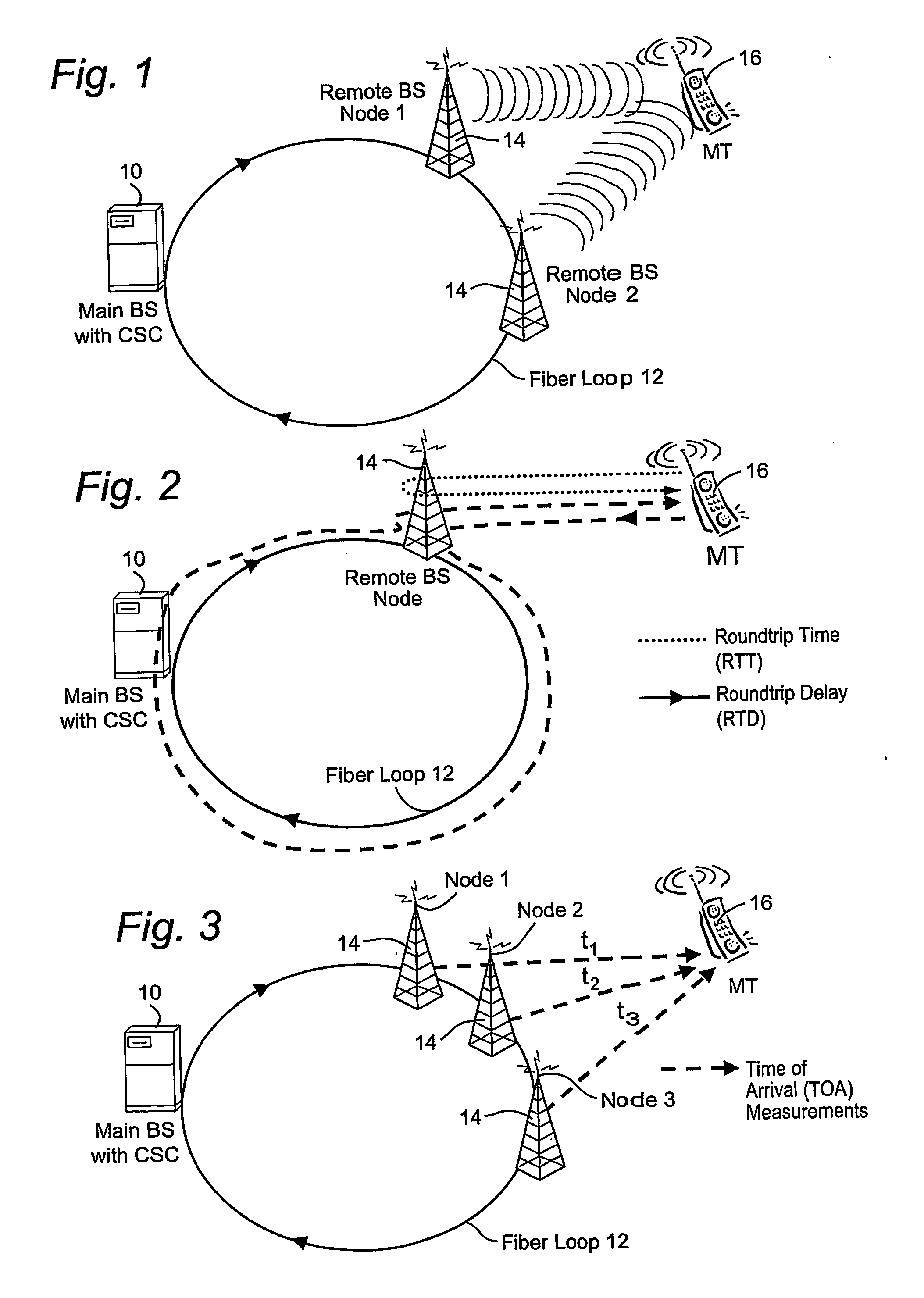
Although frequency synchronization can be achieved using a standard clock-recovery method, it is not possible to absolute time synchronize individual nodes using roundtrip measurements.
This is because the uplink and the downlink are generally not symmetrical in this case, and optical fiber transmission delay is temperature dependent.
If the temperature varies even several degrees, the time delay associated with the particular optical length may vary significantly—particularly with respect to the exacting synchronization and / or other time constraints imposed by many applications.

Method used


Image

  • Temperature compensation for transmission between nodes coupled by a unidirectional fiber ring
  • Temperature compensation for transmission between nodes coupled by a unidirectional fiber ring
  • Temperature compensation for transmission between nodes coupled by a unidirectional fiber ring

Examples


Embodiment Construction

[0030] The following description, for purposes of explanation and not limitation, sets for the specific details, such as particular components, electronic circuitry, signaling, techniques, standards, etc. in order to provide an understanding of the described technology. But it will be apparent to one skilled in the art that other embodiments may be practiced apart from the specific details. In other instances, detailed descriptions of well-known methods, devices, techniques, etc. are omitted so as not to obscure the description with unnecessary detail. For example, one advantageous application is a radio access network that employs a main-remote base station functionality. The main base station unit may communicate with the remote base station units using, for example, the common public radio interface (CPRI) specification. But other interfaces, as well as other applications, may be employed. Individual function blocks are shown in the figures. Those skilled in the art will apprecia...


PUM


Abstract

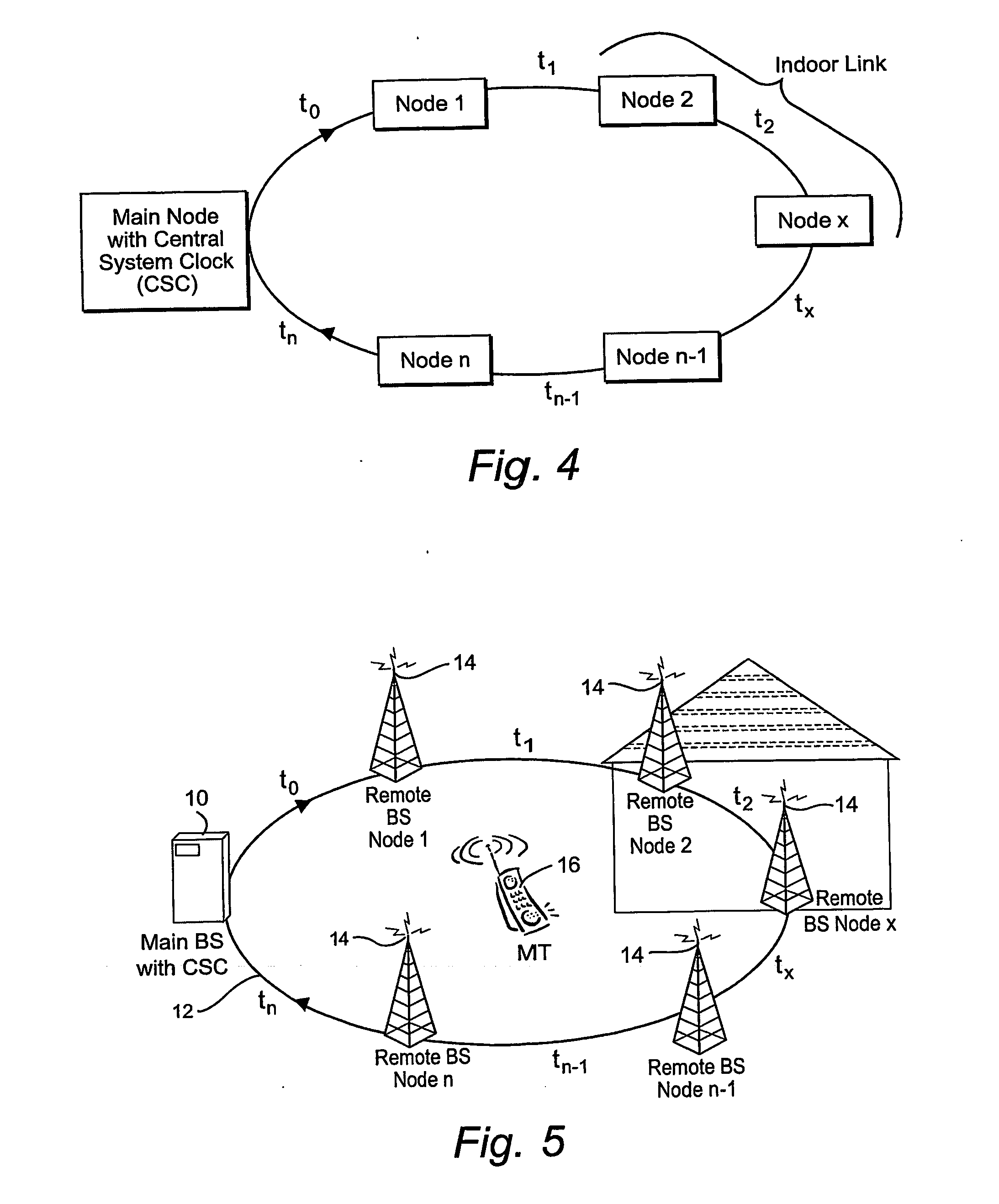
Transmissions over a unidirectional optical fiber coupling multiple nodes are compensated for temperature-induced effects. A round-trip delay time is determined for a signal sent from a first node to travel around the unidirectional optical fiber loop and be received back at the first node. That measured round-trip delay time is then used to account for temperature-induced effects on signal transmissions over the unidirectional optical fiber loop. This temperature compensation is particularly beneficial in applications that require a high level of timing accuracy.

Description

RELATED APPLICATION [0001] Priority is claimed to U.S. provisional patent application, Ser. No. 60 / 532,628, filed on Dec. 29, 2003, the entire contents of which are incorporated by reference.TECHNICAL FIELD [0002] The technology described relates temperature compensation for transmissions between remotely located nodes. Advantageous example applications include time synchronization of nodes coupled in a unidirectional, optical fiber ring or loop, and in the context of mobile radio communications, to measurements used for determining a mobile terminal location. BACKGROUND AND SUMMARY [0003] Absolute time synchronization (where the term “absolute” refers to the time-of-day) of nodes in a distributed network is important for many operations, e.g., scheduling of distributed tasks and accurately logging the occurrence of various events. In a radio access network (RAN) application, absolute time synchronization and / or very accurate timing measurements are necessary or desirable in various...

Claims


Application Information

Patent Timeline
Patent Type & Authority Applications(United States)
IPC IPC(8): H04B10/08H04B10/02
CPCH04B10/071H04B10/079H04B10/0793H04L7/0075
Inventor KALLSTENIUS, THOMAS
Owner OPTIS WIRELESS TECH LLC
Why Eureka
Try Eureka