Rolled optical film

a technology of optical film and roll, applied in the direction of instruments, other domestic objects, transportation and packaging, etc., can solve the problems of large facilities for drying up solvent, uneconomical to require subsidiary materials, and observed luminous streaks due to die lines

Inactive Publication Date: 2007-06-07
KONICA MINOLTA OPTO
View PDF15 Cites 11 Cited by
  • Summary
  • Abstract
  • Description
  • Claims
  • Application Information

AI Technical Summary

Benefits of technology

[0045] The present invention can provide optical film in which no luminous streaks due to die li...

Problems solved by technology

Polymer soluble in a solvent can be applicable, and such as norbornene type polymer film and cellulose triacetate film have been commonly utilized with respect to excellent uniformity of layer thickness, however, there were problems of such as requirement of large facilities to dry up the solvent.
Therefore, it has been uneconomical to require subsidiary materials, which are not essentially required, such as to wind up while protecting the surface with a masking film, to incorporate a slidi...

Method used


Image

  • Rolled optical film
  • Rolled optical film
  • Rolled optical film

Examples


example 1

[0137] A mixture of cellulose acetate propionate, which had been vacuum dried at 80° C. for 12 hours (a moisture ratio of 100 ppm) and had an acetyl group substitution degree of 1.95, a propionyl group substitution degree of 0.7 and a number average molecular weight of 60,000, of 100 weight parts, 10 weight parts of trimethylolpropane tribenzoate, 1.0 weight parts of Tinuvin 326, 0.1 weight part of 2,6-di-t-butyl-p-cresole, 0.1 weigh part of pentaerythrityl-tetrakis[3-(3,5-di-t-butyl-4-hydroxyphenyl)propionate] and 0.1 weight part of triisodecyl phosphite was melting mixed at 235° C. to be pelleted by use of a biaxial type extruder. At this time, not a kneading disc but a screw of an all screw type was utilized to depress heating due to sharing at the time of kneading. Further, vacuum suction through a vent was performed to suctioning remove volatile components generated during kneading. Herein, a feeder and a hopper to supply the mixture to an extruder and the midway from an extrud...

example 2

[0152] Rolled optical film having a length of 550 m, a width of 1.1 m and a thickness of 80 μm was prepared in a similar manner to example 1, except that the line pressure of a touch roll was set to 5 kN / m and a stretching magnification was set to 1.5 times.

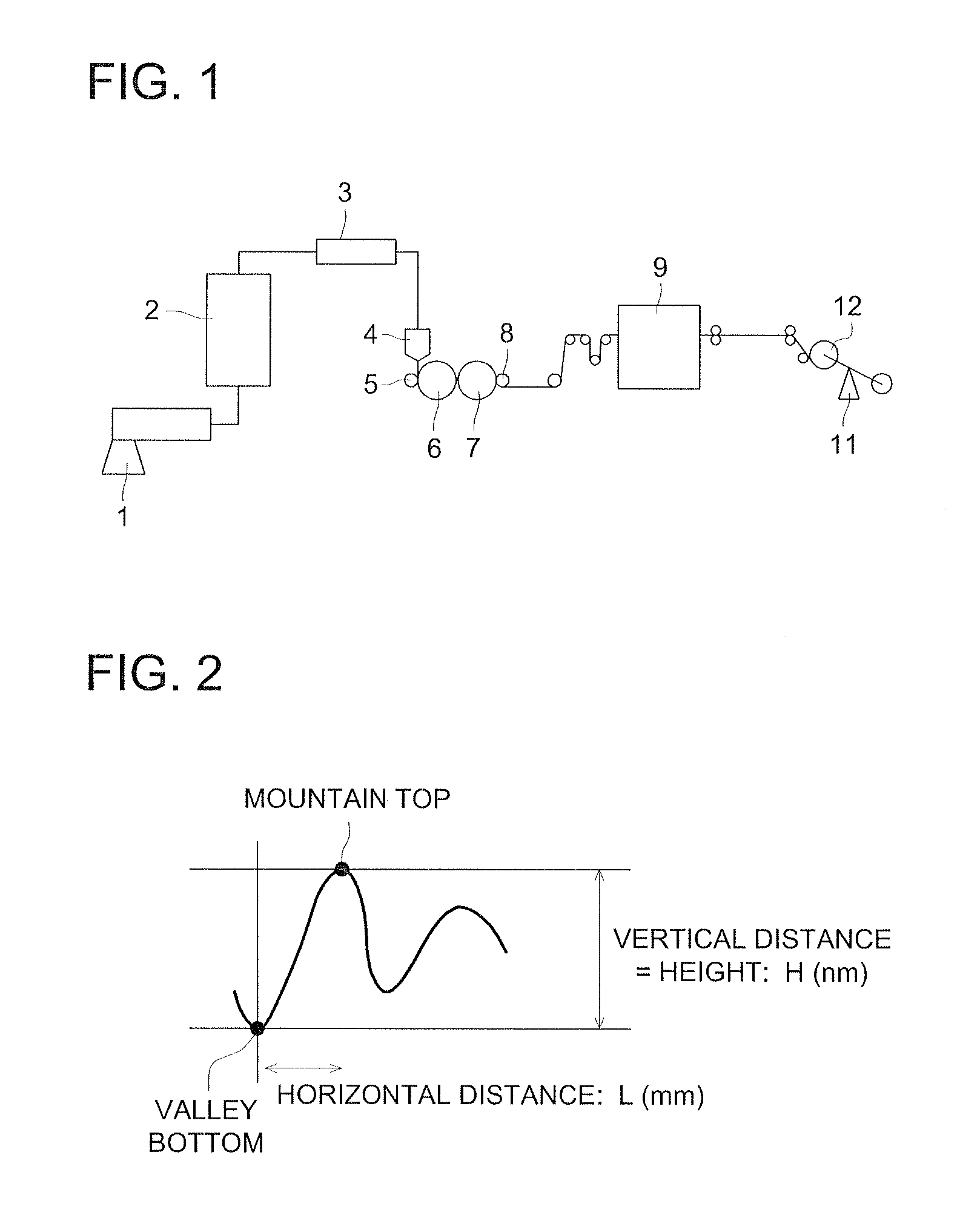
[0153] With respect to the prepared film, measurement of a form (height, inclination) and a number of streaks, Ro and Rt, and evaluations of luminous streaks and light leakage when being observed on a liquid crystal display, in a similar manner to example 1. The results are shown in table 1.

example 3

[0154] Rolled optical film, having a length of 550 m, a width of 1.1 m and a thickness of 80 μm, was prepared in a similar manner to example 1, except that the line pressure of a touch roll was set to 20 kN / m.

[0155] With respect to the prepared film, measurement of a form (height, inclination) and a number of streaks, Ro and Rt, and evaluations of luminous streaks and light leakage when being observed on a liquid crystal display, in a similar manner to example 1. The results are shown in table 1.


PUM

PropertyMeasurementUnit
Lengthaaaaaaaaaa
Lengthaaaaaaaaaa
Lengthaaaaaaaaaa

Abstract

A rolled optical film includes a cellulose ester film which has a width of from 1 m to 3 m and a length of 500 m or more and is shaped in a rolled film. The cellulose ester film includes streaks from 1 line to 20 lines per 10 mm in a lateral direction thereof in which the streaks have a height of from 50 nm to 300 nm, an inclination of from 50 nm/mm to 300 nm/mm and a continuous length of 50 cm or more in a longitudinal direction thereof and the cellulose ester film does no includes a streak which has a height of 300 nm or more, an inclination of 300 nm/mm or more and a continuous length of 50 cm or more in a longitudinal direction thereof.

Description

[0001] This application is based on Japanese Patent Application No. 2005-350287 filed on Dec. 5, 2005 in Japanese Patent Office, the entire content of which is hereby incorporated by reference. BACKGROUND OF THE INVENTION [0002] The present invention relates to rolled optical film, which shows no light leakage and no luminous streaks due to die lines when being viewed on a liquid crystal display, even without utilizing masking film and a sliding agent. [0003] A liquid crystal display has been commonly utilized as a monitor due to advantages of space saving and energy saving compared to a conventional CRT display. Further, it has been popularized as a TV application. In such a liquid crystal display, utilized are various types of optical film such as polarizer film, phase difference film, anti-reflection film and luminance enhancing film. [0004] Polarizer film is comprised of a polarizer element made of stretched polyvinyl alcohol film on one surface or the both surfaces of which cel...

Claims


Application Information

Patent Timeline
IPC IPC(8): C09K19/00B29C48/08B29C48/305
CPCB29C47/0021Y10T428/1041B29C47/8845B29C55/04B29C55/12B29K2001/00B29K2001/12B29K2105/256C08J5/18C08J2301/10G02B1/105Y10S428/906Y10T428/24479Y10T428/105B29C47/14Y02P20/582B29C48/08B29C48/305B29C48/914B29C48/9155G02B1/14C09K2323/035C09K2323/031
Inventor YAJIMA, TAKATOSHI
Owner KONICA MINOLTA OPTO
Why Eureka
Try Eureka