Furnace alignment system

a technology of alignment system and pusher furnace, which is applied in the direction of muffle furnace, furnace, charge manipulation, etc., can solve the problems of increasing the potential for slide plate jamming, affecting the stability and affecting the operation of the pusher furna

Active Publication Date: 2007-06-07
AJAX MAGNETHERMIC CORP
View PDF23 Cites 28 Cited by
  • Summary
  • Abstract
  • Description
  • Claims
  • Application Information

AI Technical Summary

Problems solved by technology

In addition, many pusher furnaces are relatively short and heated to relatively low temperatures, sometimes only with resistance heating mechanisms.
This increases the potential for jamming of the slide plates as they move through the furnace.
Likewise, it is necessary to maintain these seals during cooling of the furnace, which causes contraction of these various structures.

Method used


Image

  • Furnace alignment system
  • Furnace alignment system
  • Furnace alignment system

Examples


Embodiment Construction

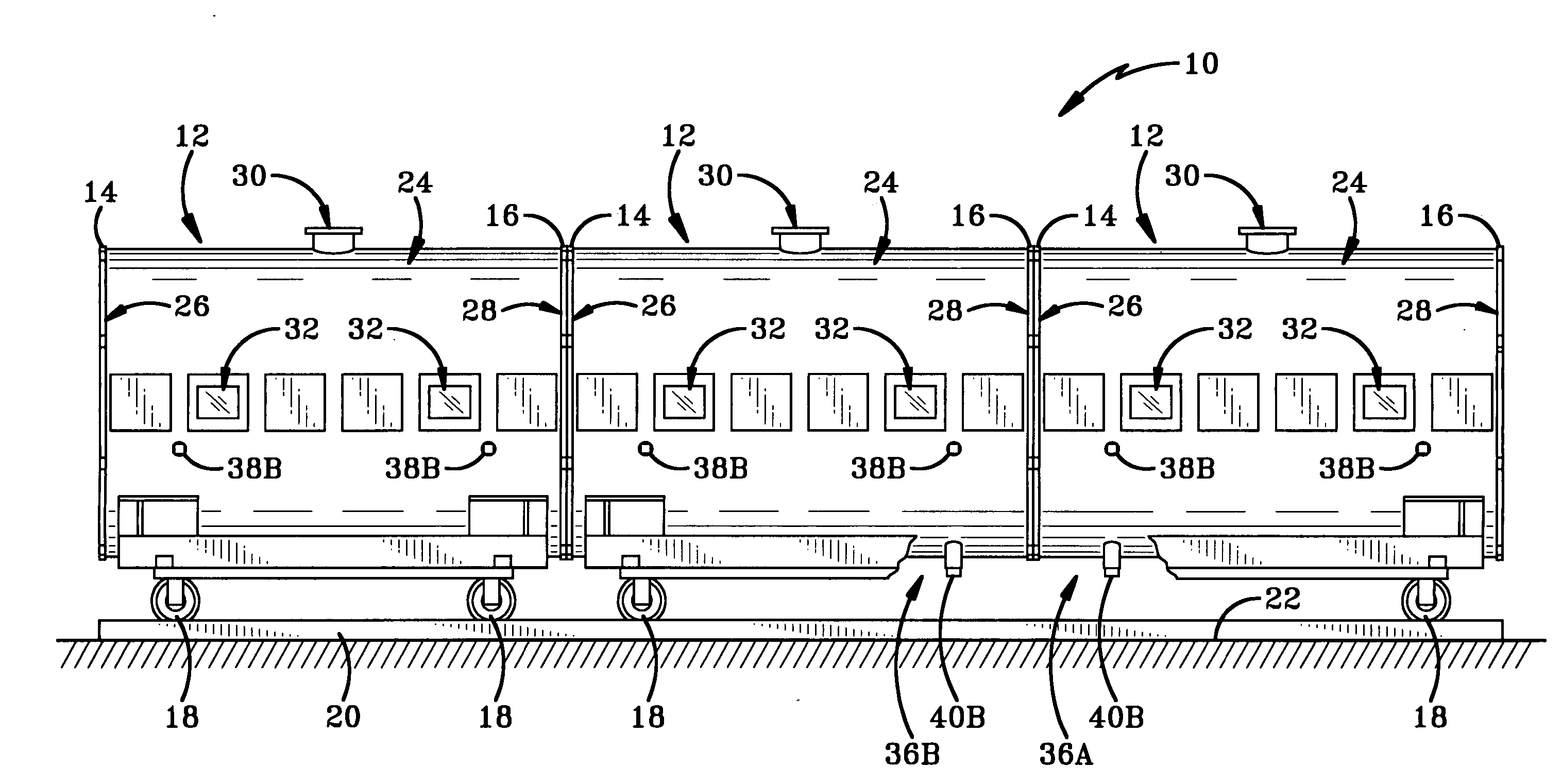
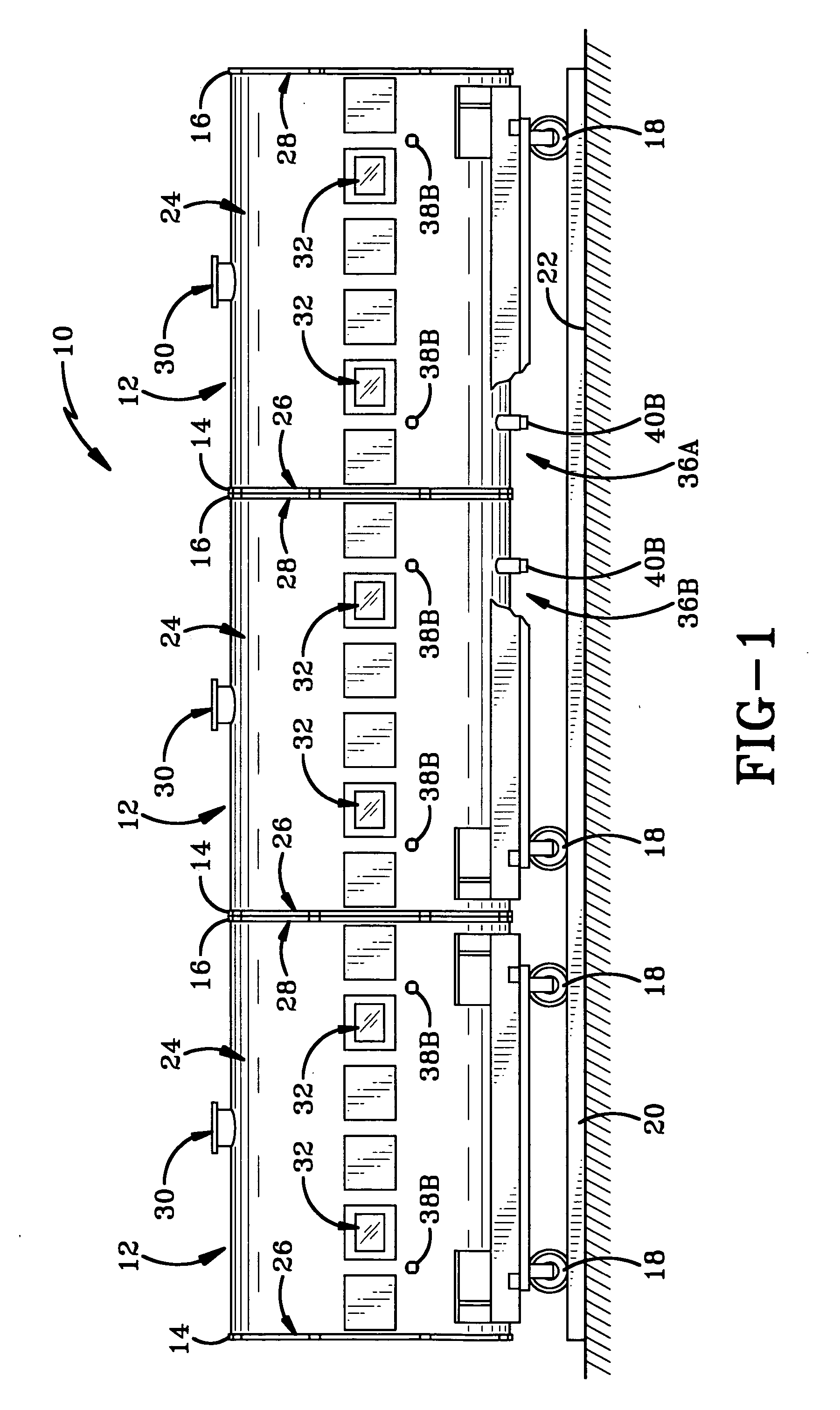
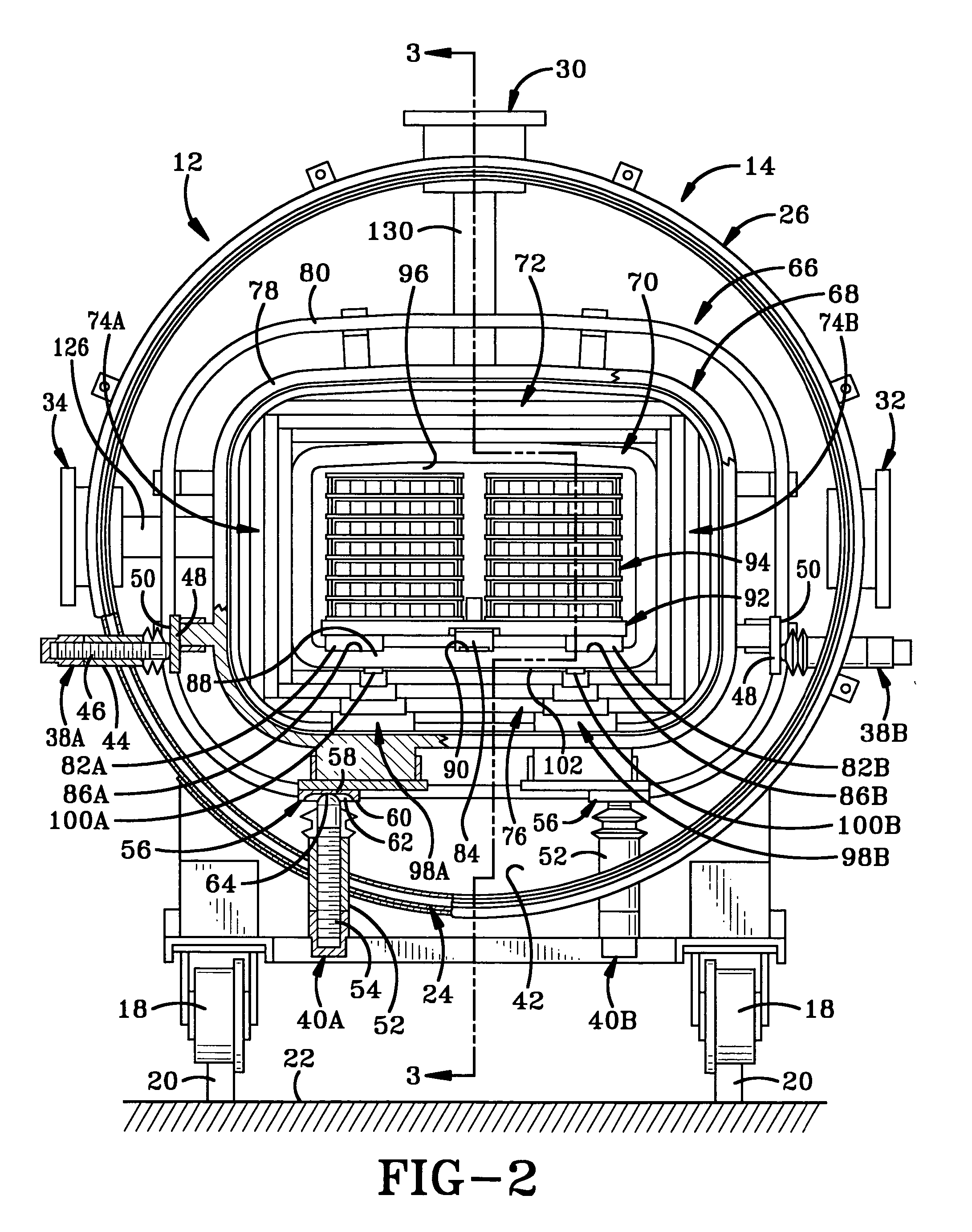
[0019] The pusher furnace of the present invention is indicated generally at 10 in FIG. 1. Furnace 10 includes a plurality of furnace sections 12 which are identical or substantially the same as one another. The furnace section 12 has a first or upstream end 14 and a second or downstream end 16 opposed thereto wherein first and second ends 14 and 16 define therebetween a longitudinal direction of the furnace section which is the same for furnace 10. Each of furnace sections 12 is generally supported on wheels 18 which roll on spaced tracks 20 which are seated atop a supporting surface 22 such as a floor or the like. Furnace section 12 includes a double walled outer vessel 24 having first and second mounting flanges 26 and 28 disposed respectively adjacent first and second ends 14 and 16 thereof for mounting to adjacent furnace section 12 via fasteners, such as bolts or the like (not shown). Each furnace section 12 includes an exhaust port 30, a pair of first sight ports 32 and a pai...


PUM


Abstract

A pusher furnace includes furnace sections having respective susceptors, a slide rail extending through the furnace sections for sliding pusher plates thereon and an alignment assembly for aligning the susceptors and slide rails of adjacent furnace sections. A support structure spaces the susceptors from insulation therebelow to protect the insulation from degradation from contact with the susceptors. The susceptors are slidably mounted on the support structure to accommodate thermal expansion and shrinkage of the susceptor. The upstream end of the slide rails have beveled upper edges to help prevent the pusher plates from catching thereon. The upstream ends are also laterally tapered to reduce the degree of force encountered should a pusher plate catch thereon. Adjacent insulation members have expansion joints filled with a refractory felt. The susceptors slidably and sealingly engage exhaust ports to allow for thermal expansion and shrinkage of the susceptor without damaging the exhaust port.

Description

CROSS REFERENCE TO RELATED APPLICATIONS [0001] This application claims priority from U.S. Provisional Application Ser. No. 60 / 748,819 filed Dec. 7, 2005; the disclosure of which is incorporated herein by reference.BACKGROUND OF THE INVENTION [0002] 1. Technical Field [0003] The invention relates generally to pusher furnaces. More particularly, the invention relates to a pusher furnace having an alignment mechanism for aligning multiple furnace sections which are joined to one another to make up a portion of the furnace. Specifically, the invention relates to such a pusher furnace which is configured to control the expansion of insulation and other structures within each furnace section while allowing the thermal expansion and contraction of an inductively heated susceptor over the length of the furnace sections while minimizing degradation of the insulation and providing for smooth continuous movement of pusher plates through the furnace. The furnace is able to repeatedly cool and r...

Claims


Application Information

Patent Timeline
Patent Type & Authority Applications(United States)
IPC IPC(8): F27D3/00
CPCF27B9/029F27B9/067F27B9/22F27B9/34F27B9/36F27D3/0021F27D3/02Y02P10/25
Inventor TENZEK, ANTHONY M.LAZOR, DAVID A.
Owner AJAX MAGNETHERMIC CORP
Why Eureka
Try Eureka