
Three-dimensionally reinforced multifunctional nanocomposites

a nano-composites, multi-functional technology, applied in the field of composite materials, can solve the problems of low interlaminar fracture toughness of cfrcs, and weakness of 1-d and 2-d cfrcs, and achieve the effect of improving the reinforcement structur

Active Publication Date: 2007-06-07
RENESSELAER POLYTECHNIC INST +1
View PDF5 Cites 186 Cited by
  • Summary
  • Abstract
  • Description
  • Claims
  • Application Information

AI Technical Summary

Benefits of technology

[0014] Another embodiment comprises a fabric reinforcement and a method of manufacturing the same comprising a woven fiber cloth and carbon nanotubes connected to the woven fiber cloth. The nanotubes extend generally perpendicular to the woven fiber cloth. A plurality of such fabric reinforcements may be joined together to provide an improved reinforcement structure.

Problems solved by technology

However, an inherent weakness of 1-D and 2-D CFRCs is their interlaminar and intralaminar properties.
As 1-D and 2-D CFRCs lack reinforcement out of the plane of the fibers, they possess little resistance to out of plane deformation.
As a result, these CFRCs possess low interlaminar fracture toughness, and interlaminar failure, such as delamination, may occur at relatively low levels of applied stress under various loading conditions.
However, attempts to develop these 3-D reinforced composites employing braided or through-the-thickness stitched fibers have met with mixed success.
Investigations of composite laminates with 3-D braided reinforcements have found improvements in damage tolerance but also determined that the braided reinforcement and the non-normal orientation of the braided fiber with the 2-D in-plane fiber results in low in-plane strengths.
The low in-plane strengths limit the applicability of the 3-D braided composites to specific applications and geometries.
However, lack of control of the orientation of the nanotubes and their dispersion is still a major challenge and indeed restricts their usage in structural applications

Method used


Image

  • Three-dimensionally reinforced multifunctional nanocomposites
  • Three-dimensionally reinforced multifunctional nanocomposites
  • Three-dimensionally reinforced multifunctional nanocomposites

Examples


examples

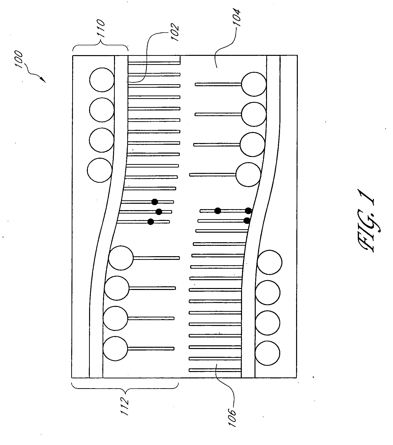
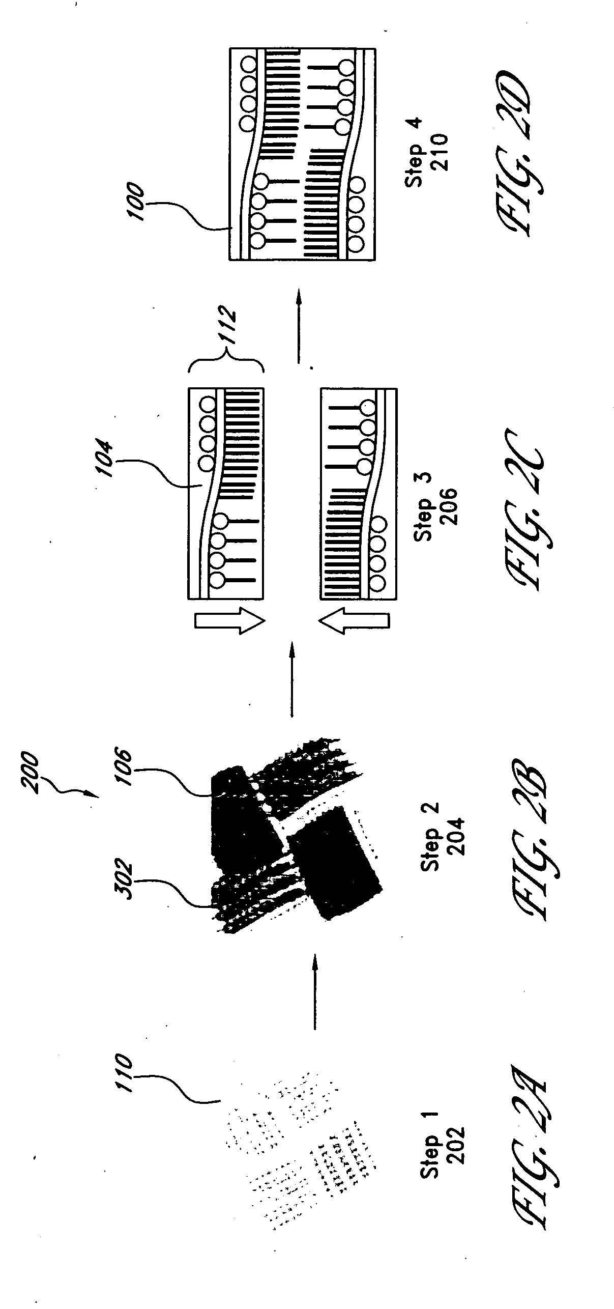
[0049] In the following examples, testing is performed on 3-D nanocomposites and their 2-D counterparts to illustrate the property improvements which may be achieved through embodiments of the 3-D nanocomposite 100. In particular, in-plane and interlaminar mechanical properties, mechanical damping, thermoelastic response, and thermal and electrical conductivities are examined. The 3-D nanocomposites 100 tested are laminates formed as described above, using a 3-D fiber preform 302 of SiC plain-weave fiber cloths having CVD-grown MWCNTs extending approximately perpendicular to the plane of the SiC fiber cloth and a matrix of DGEBPA-AE. The nanocomposites further possess weight fractions of the matrix, SiC fiber cloth, and CNTs of approximately 35%, 63%, and 2%, respectively. To assess the influence of the through-thickness CNTs on performance of the 3-D nanocomposites 100, 2-D baseline composites were similarly formed without the MWCNT reinforcement.

[0050] Studies are also presented ...

examples 1-4

Interlaminar fracture

[0051] Examples 1-4 illustrate the advantages of using of 3-D nanocomposites over their 2-D counterparts to increase the delamination resistance of the composite. One of the most commonly observed damage modes in laminated composites is the separation of adjacent plies, or delamination. Delamination in laminated composites may arise from one of the many events, including low velocity impacts, fatigue loadings, eccentricities in the load path, or by geometric and structural discontinuities, such as holes, edges, or ply drops, that act as stress raisers within the area adjacent to the discontinuity. With the increased use of laminated fiber reinforced composite materials in primary aircraft and marine structural components, delamination failure is a significant concern. Therefore, interlaminar fracture toughness testing is performed to determine interlaminar fracture toughness for two different modes of loading, Mode I, an opening mode, and Mode II, a sliding mod...

examples 5-6

In-plane Mechanical Characterization

[0057] Examples 5-6 illustrate the effect of CNTs on the in-plane mechanical properties of 2-D baseline composites and 3-D nanocomposites. The in-plane tensile strength, elastic modulus, and flexural toughness of the two composite systems are measured by 3-point, in-plane flexure loading based upon ASTM Standard D790-00, titled, “Standard Test Methods for Flexural Properties of Unreinforced and Reinforced Plastics and Electrical Insulating Materials.” Average values for three test specimens are reported in Table 2 below, with the percent change in the 3-D nanocomposite property values over the 2-D baseline composite in parentheses.

TABLE 2GIC of 2-D baseline composites and 3-D nanocomposites.FlexuralFlexuralFlexuralStrengthModulusToughnessExampleMaterials(MPa)(GPa)(N mm)5C2-D Baseline 62.1 ± 2.123.1 ± 0.35.8Composites63-D Nanocomposites150.1 ± 1.424.3 ± 0.230.4(240%)(105%)(524%)

[0058] Examples 5-6 demonstrate that the through-thickness CNTs may ...


PUM

PropertyMeasurementUnit
Volumeaaaaaaaaaa
Volumeaaaaaaaaaa
Volumeaaaaaaaaaa

Abstract

A three-dimensional composite reinforcement, a three-dimensionally reinforced multifunctional nanocomposite, and methods of manufacture of each are disclosed. The three dimensional reinforcement comprises a two dimensional fiber cloth upon which carbon nanotubes have been grown, approximately perpendicular to the plane of the fiber cloth. The nanocomposite comprises the three-dimensional reinforcement and a surrounding matrix material. Examples illustrate improvements in the through-thickness mechanical, thermal, and electrical properties of the nanocomposite, in addition to substantial improvements in geometrical stability upon temperature changes and vibrational damping, compared to baseline composites reinforced with the two-dimensional fiber cloth alone. Embodiments of the nanocomposite may also be configured to perform multiple functions simultaneously, such as bearing a thermal or mechanical load simultaneously or bearing a mechanical load while also monitoring the state of damage within the nanocomposite.

Description

CROSS-REFERENCE TO RELATED APPLICATIONS [0001] This application claims the benefit of priority under 35 U.S.C. §119(e) of U.S. Provisional Application No. 60 / 740,461 filed on Nov. 28, 2005, the entirety of which is incorporated herein by reference.STATEMENT REGARDING FEDERALLY SPONSORED R&D [0002] This invention was made with Government support under Contract Numbers N00014-00-1-0692 and N00014-05-1-05086 awarded by ONR (Office of Naval Research) and Contract Number NSEC0117792 awarded by NSF (National Science Foundation). The Government has certain rights in this invention.PARTIES OF JOINT RESEARCH AGREEMENT [0003] This invention was made as a result of activities undertaken within the scope of a joint research agreement between the University of Hawaii and Rensselaer Polytechnic Institute. BACKGROUND OF THE INVENTION [0004] 1. Field of the Invention [0005] Certain embodiments of the present invention relate to composite materials and, in particular, woven fiber composites reinforc...

Claims


Application Information

Patent Timeline
IPC IPC(8): B32B5/02B32B27/04B32B17/02B32B3/00
CPCB82Y30/00C04B35/62863C04B35/62884C04B41/009C04B41/52C04B2235/5244C04B2235/5248C04B2235/5268C04B2235/5288C08J5/005C08J5/047C08J2363/00C04B14/026C04B41/4529C04B41/4853C04B41/4826C04B41/522C04B14/386C04B30/02C04B14/4693B29C70/02Y10S977/742Y10S977/753B29K2105/124B29C70/081B29C70/24Y10T442/2984Y10T442/2418Y10T442/2992Y10T442/2926Y10T442/20Y10T442/2975Y10T442/2426Y10T442/3472C08J5/00B32B27/04
Inventor GHASEMI NEJHAD, MOHAMMAD NAGHIVEEDU, VINOD P.CAO, ANYUANAJAYAN, PULICKELASKARI, DAVOOD
Owner RENESSELAER POLYTECHNIC INST
Learn More