
Queuing system, method and computer program

Inactive Publication Date: 2007-06-07
ORDERLY MIND LTD
View PDF32 Cites 61 Cited by
  • Summary
  • Abstract
  • Description
  • Claims
  • Application Information

AI Technical Summary

Benefits of technology

[0033] The subsequent request for service from the customer terminal may be initiated by the customer or may be initiated automatically. The method of the present invention allows customers to make a request for service and then disconnect. Their place in the queue is saved and when they reconnect they return to their place in the queue, possibly being served immediately.
[0044] validating the subsequent request for service by comparing the first encrypted string with the second encrypted string. This prevents users jumping the queue.
[0048] validating the request for service by comparing the encrypted queue server string with a service host encrypted string constructed at the service host using the secret phrase and information specific to the request for service and information specific to the queue server. This prevents customers bypassing the queue server.
[0087] Preferably, the means to send the queue identifier to the customer terminal is adapted to send additional information relating to the queue to the customer terminal with the queue identifier. Preferably, the additional information includes a service number, the service number being an indication of the queue identifier currently being served. Preferably, in use, the queue server increments the service number automatically at a constant rate. Preferably, in use, the queue server increments the service number automatically, the rate of increment being varied in dependence on the number of requests for service forwarded to the service host. Ideally, the rate at which the service number is incremented can be controlled.

Problems solved by technology

Any service provided over a communications network will have limited bandwidth, resulting in a maximum number of customers that can be served per minute.
The bandwidth may be limited for technical reasons, such as web service speed or the number of incoming phone lines, or may be limited because there are simply not enough operators to handle the demand for service.
However, when demand is greater than the maximum possible service rate, problems can occur unless a traffic management system is employed.
Fans, knowing that tickets are limited, will all try to use the system as soon as the tickets go on sale, creating a demand “spike” that may well be above the maximum transaction rate that the system can cope with.
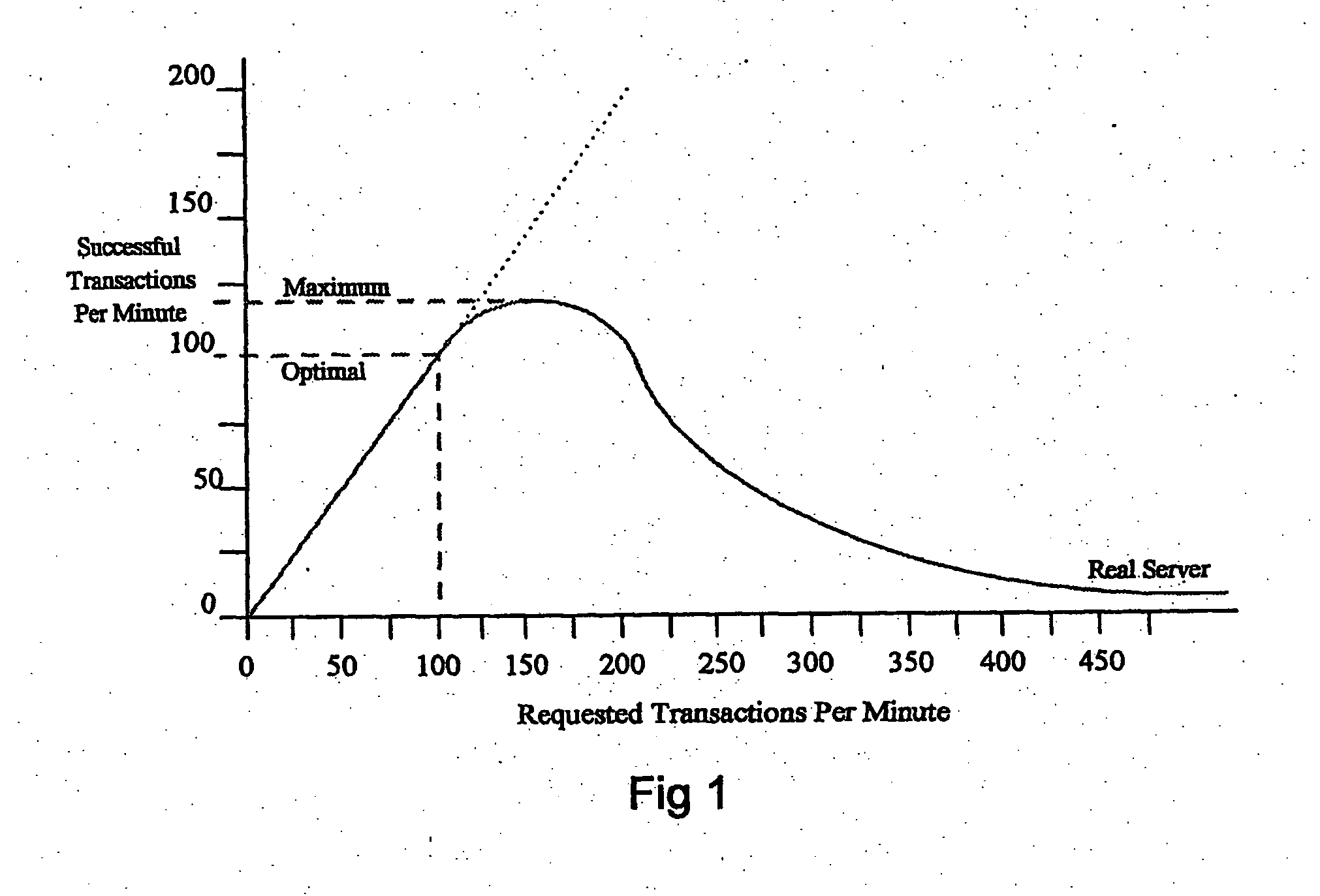
The number of users who can successfully complete this path concurrently is limited by the bandwidth of the system, which in turn is limited by the bandwidth of the most resource intensive step.
As requested rates increase beyond this, some transactions will fail, resulting in frustrated users.
Payment gateways may have an optimum transaction rate of about 100 successful transactions per minute, although most payment gateways are much less efficient than this.
This causes an additional request to be sent to the payment gateway, which must also be dealt with, further increasing the server load.
Furthermore, as the payment gateway fails, users may start to jam up the earlier stages of the e-commerce path, resulting in saturated payment pages (stage 2) and eventually a saturated web server (stage 1).
This problem is particularly significant if all these stages reside on the same physical machine.
As stated above, this situation is particularly serious when there is a very high interest in the particular product which is available in limited quantities and goes on sale at a particular time.
Catastrophic failure then propagates backward through the system.
Catastrophic failure will last as long as customers continue to submit requests and for popular events can last for many hours.
This creates a number of problems.
Firstly, the experience of buying a product or service is protracted and is extremely frustrating, creating negative publicity for the service providers.
Customers become angry that their time is being wasted.
Secondly, customers perceive that the assignment of successful transactions is random or based on the whims of the networking hardware, leading to intense dissatisfaction.
Thirdly, the server load means that attempts to modify the pages to improve the system “on the fly” may not succeed.
If the high load has been anticipated, certain checks (such as credit card authorisation) may be postponed until after the ‘sale’ to increase performance, causing further work and uncertainty as to the number of tickets actually sold.
The server load means that attempts must be made to increase capacity at an additional cost to the vendor and ultimately to the customer.
A simple but expensive solution to some of these problems is to increase the bandwidth of the most limited part of this system, usually the payment gateway, by adding additional servers in parallel.
In practice, if the payment gateway is the bottleneck for the process, it is in general not possible to scale up its capacity to meet arbitrary demand rates.
Firstly, the bandwidth of the credit card network is usually limited and secondly, the bandwidth of the database system that stores the transactions is limited.
Database servers are very expensive to scale and there are often technical reasons why the number of database servers cannot be increased beyond two.
Whilst adding servers may allow a vendor in practice to double the transaction rate, the actual level of demand for a particular product cannot be accurately predicted and the risk of catastrophic failure for very high interest sales is not reduced.
All that is achieved is further expense both in hardware and in staffing costs.
Finally, in real e-commerce, servers more frequently fail for reasons other than excess demand.
Examples include network or power outages, hardware faults, system updates or reboots, and software errors.
In these cases too, customers are prevented from obtaining offered products and services, frequently being presented with an error message instead of the desired successful transaction.
Unless a service provider is alerted to a failure and performs the necessary repairs, these customers may be lost.

Method used


Image

  • Queuing system, method and computer program
  • Queuing system, method and computer program
  • Queuing system, method and computer program

Examples


Embodiment Construction

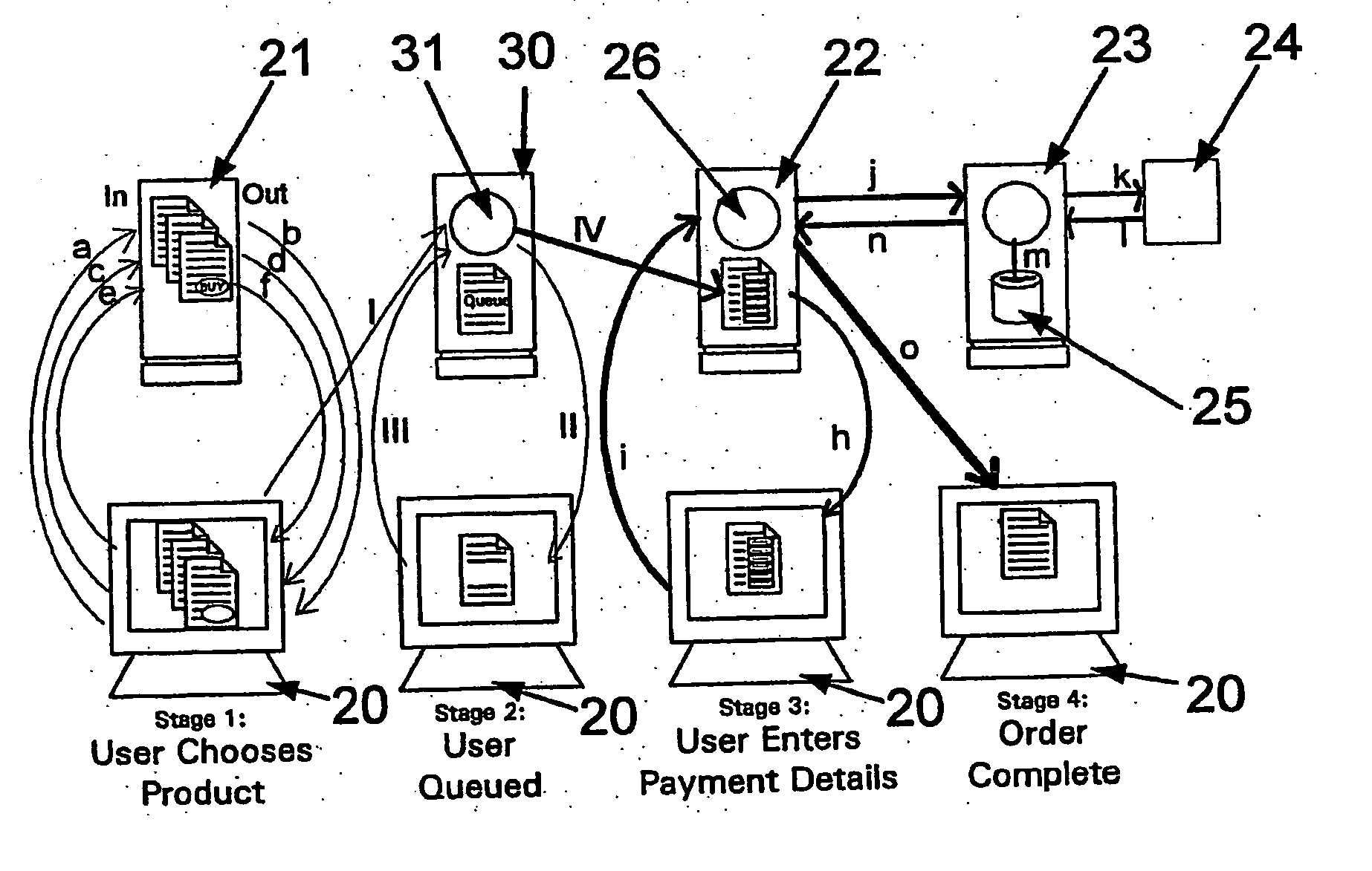
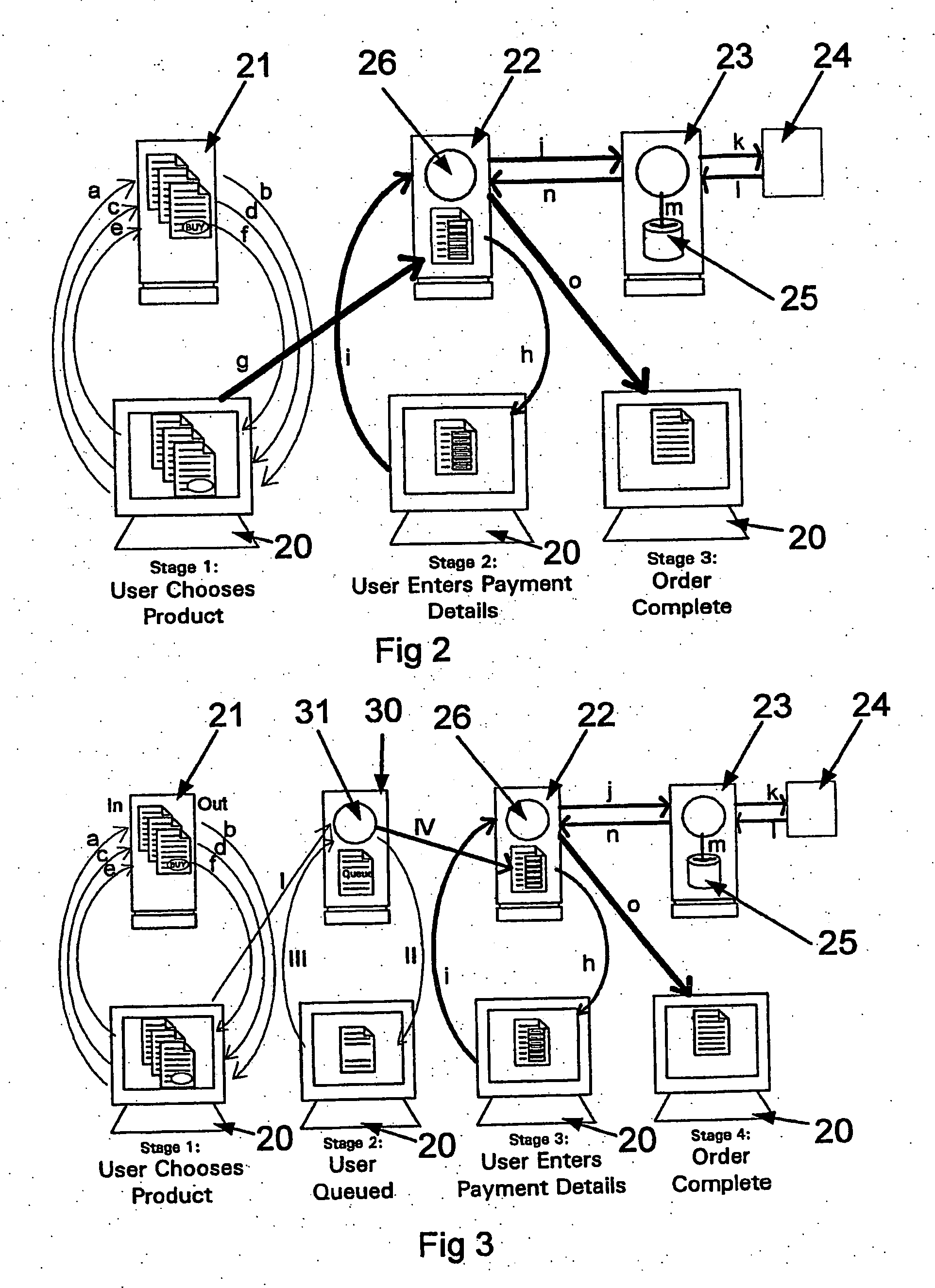
[0109]FIG. 2 illustrates a typical non-queued e-commerce system. The customer has a customer terminal 20. The customer terminal is shown three times in order to represent the three phases the user goes through during a purchase. The purchase depicted in FIG. 2 consists of the following steps, indicated by arrows (a)-(o).

[0110] a) The user makes an HTTP (HyperText Transfer Protocol) request of a web server 21.

[0111] b) The web server 21 responds with an HTTP response containing an HTML (Hyper Text Markup Language) page. The page is displayed on the user's screen.

[0112] c) The user clicks on links to select other pages, or products to buy, resulting in further requests.

[0113] d) This results in further responses from the web server 21 containing different pages. If a user clicks on a link that indicates a product has been chosen, that information is stored on the server (not shown).

[0114] e) Eventually, the user must click on a link that causes the server to respond . . .

[0115] ...


PUM


Abstract

The present invention provides a method for managing requests for service over a communications network. The method of the invention comprises the steps of: receiving a request for service from a customer terminal at a queue server via the communications network; allocating a queue identifier to the request for service; sending the queue identifier to the customer terminal; receiving the queue identifier from the customer terminal at the queue server as part of a subsequent request for service; performing a comparison between the queue identifier and queue status information; and forwarding the request for service to the service host in accordance with the result of the comparison. Preferably, if sufficient resources are available, the request for service is forwarded directly to the service host without entering a queue. If there are insufficient resources, the request for service is held in an automatically managed queue and the risk of catastrophic failure is eliminated.

Description

CROSS-REFERENCE [0001] This application is a U.S. National Stage filing under 35 U.S.C. §371 and 35 U.S.C. §119, based on the claiming priority to GB 0410829.6, GB 0500801.6 and PCT / GB2005 / 01854 for “QUEUING SYSTEM, METHOD AND COMPUTER PROGRAM PRODUCT FOR MANAGING THE PROVISION OF SERVICES OVER A COMMUNICATIONS NETWORK”.FIELD OF THE INVENTION [0002] The present invention relates to the provision of services over a communications network having limited bandwidth, due to a limitation of the network or limitation on server resources. BACKGROUND TO THE INVENTION [0003] Any service provided over a communications network will have limited bandwidth, resulting in a maximum number of customers that can be served per minute. The bandwidth may be limited for technical reasons, such as web service speed or the number of incoming phone lines, or may be limited because there are simply not enough operators to handle the demand for service. [0004] When demand is less than the maximum possible ser...

Claims


Application Information

Patent Timeline
IPC IPC(8): G06F15/173G06Q10/00H04L29/06H04L29/08
CPCH04L67/34H04L67/2819H04L67/02H04L67/32H04M3/5231H04L67/564H04L67/60H04M3/523H04Q3/0029H04Q3/64H04L67/562
Inventor KING, MATT
Owner ORDERLY MIND LTD
Learn More