Storage system and capacity allocation method therefor

a storage system and capacity allocation technology, applied in memory systems, sustainable buildings, instruments, etc., can solve the problems of insufficient original storage capacity of the storage system bought by the user, increased power consumption of hard disk drives, and increased power consumption of storage systems that implement on-demand services. the effect of reducing the power consumption of the storage system

Inactive Publication Date: 2007-06-07
HITACHI LTD
View PDF5 Cites 29 Cited by
  • Summary
  • Abstract
  • Description
  • Claims
  • Application Information

AI Technical Summary

Benefits of technology

[0013] Because powered disks are given priority in allocation to logical disks, an increase in the power consumption of the storage system that implements an on-demand service can be minimized.

Problems solved by technology

At present, storage systems with a plurality of hard disk drives installed therein are used as storage systems to store such information, but because these hard disk drives consume a large amount of electricity, demand continues to exist for hard disk drives that consume less power.
Furthermore, there are situations in which the original storage capacity of the storage system bought by the user is insufficient, and additional hard disk drives must be purchased.
In the technologies described in Patent Documents 1 and 2, where the storage capacity allocated to the user is increased, the amount of power consumption increases in tandem with the expansion in storage capacity, but insufficient attention has been paid to reducing this power consumption.

Method used


Image

  • Storage system and capacity allocation method therefor
  • Storage system and capacity allocation method therefor
  • Storage system and capacity allocation method therefor

Examples


first embodiment

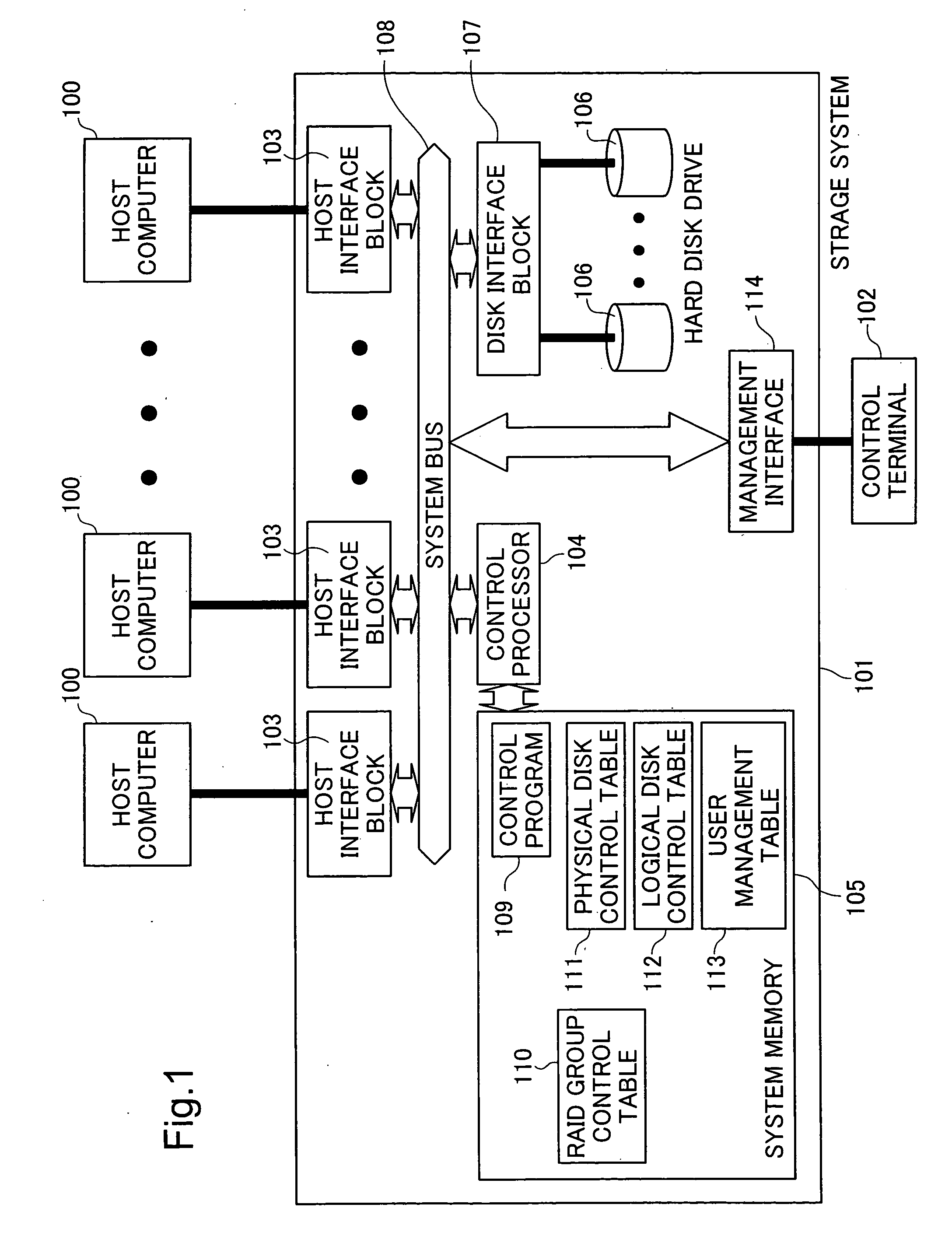
[0033]FIG. 1 is a block diagram showing the hardware configuration of a computer system of a first embodiment. This computer system comprises a plurality of host computers 100, a storage system 101 and a control terminal 102 used by an administrator to operate the storage system 101. The storage system 101 comprises a plurality of host interfaces block 103 that controls communication with the host computer 100, a management interface 114 that controls communication with the control terminal 102, a control processor 104 that controls the storage system as a whole, a system memory 105 that stores control programs executed by the control processor 104 to control the storage system, hard disk drives 106 that store data, a disk interface block 107 that carries out control of the hard disk drives 106 and communication with the hard disk drives 106, and a system bus 108 that connects the host interface block 103, control processor 104, disk interface block 107 and management interface 114 ...

second embodiment

[0096] In the first embodiment, it is assumed that when a logical disk is allocated to a user, the user starts off using the total capacity of that logical disk. In other words, it is assumed that the physical disk(s) corresponding to the logical disk allocated to the user are powered.

[0097] However, it does not necessarily mean that the user who is allocated a logical disk immediately begin using the entire capacity of the physical disk(s) corresponding to the allocated logical disk. It is expected that actual usage will resemble the situation shown in FIG. 12.

[0098]FIG. 12 shows the changes in the capacity of the storage system used by the user over time. The vertical axis 1200 represents the storage capacity used by the user, while the horizontal axis 1201 represents time. The stepped line 1202 in FIG. 12 represents the capacity of the logical disk allocated to the user. The curved line 1203 represents, out of the total capacity allocated to the user, the actually used capacity...


PUM


Abstract

A storage system connected to a terminal, the computer system includes: a plurality of drive devices that respectively drive a plurality of physical disks each having a physical storage area; a RAID configuration unit that configures a plurality of RAID groups by grouping two or more of the plurality of physical disks; a logical disk creation unit that creates, for the terminal through the RAID group, a logical disk having a logical storage area associated with the physical storage area; a memory for storing a RAID group control table showing, for each the RAID group, (i) a free capacity that is the amount of physical storage area remaining in the RAID group to be able to be associated with the logical disk and (ii) a power status of the RAID group; a receiver that receives a request for creating a new logical disk; and an area allocation unit that allocates to the new logical disk the physical storage area remaining in the RAID group selected by giving priority to a RAID group in a powered state over a RAID group in a non-powered state with reference to the RAID group control table.

Description

CROSS-REFERENCES TO RELATED APPLICATION [0001] This application relates to and claims priority from Japanese Patent Application No. P2005-348690, filed on Dec. 2, 2005, the entire disclosure of which is incorporated herein by reference. BACKGROUND [0002] 1. Technical Field [0003] The present invention relates to a computer system, and more particularly, to a control method for reducing the amount of power consumed by such device by managing the storage capacity thereof. [0004] 2. Related Art [0005] In recent years, as information technology has advanced, the amount of information used by companies, government agencies and individuals has increased dramatically. This trend has led to a demand for storage systems with much higher storage capacities. [0006] At present, storage systems with a plurality of hard disk drives installed therein are used as storage systems to store such information, but because these hard disk drives consume a large amount of electricity, demand continues to ...

Claims


Application Information

Patent Timeline
Patent Type & Authority Applications(United States)
IPC IPC(8): G06F12/16
CPCG06F3/0607G06F3/0608G06F3/0625G06F3/0631G06F3/0665G06F3/0689Y02B60/1246Y02D10/00
Inventor HASHIMOTO, AKIYOSHIYAMAMOTO, YASUTOMOFUJIBAYASHI, AKIRA
Owner HITACHI LTD
Why Eureka
Try Eureka