Smart fuel control system
a fuel control system and intelligent technology, applied in the direction of engines, machines/engines, mechanical equipment, etc., can solve the problems of fuel system overheating, fuel overheating, and fuel overheating
- Summary
- Abstract
- Description
- Claims
- Application Information
AI Technical Summary
Benefits of technology
Problems solved by technology
Method used
Image
Examples
Embodiment Construction
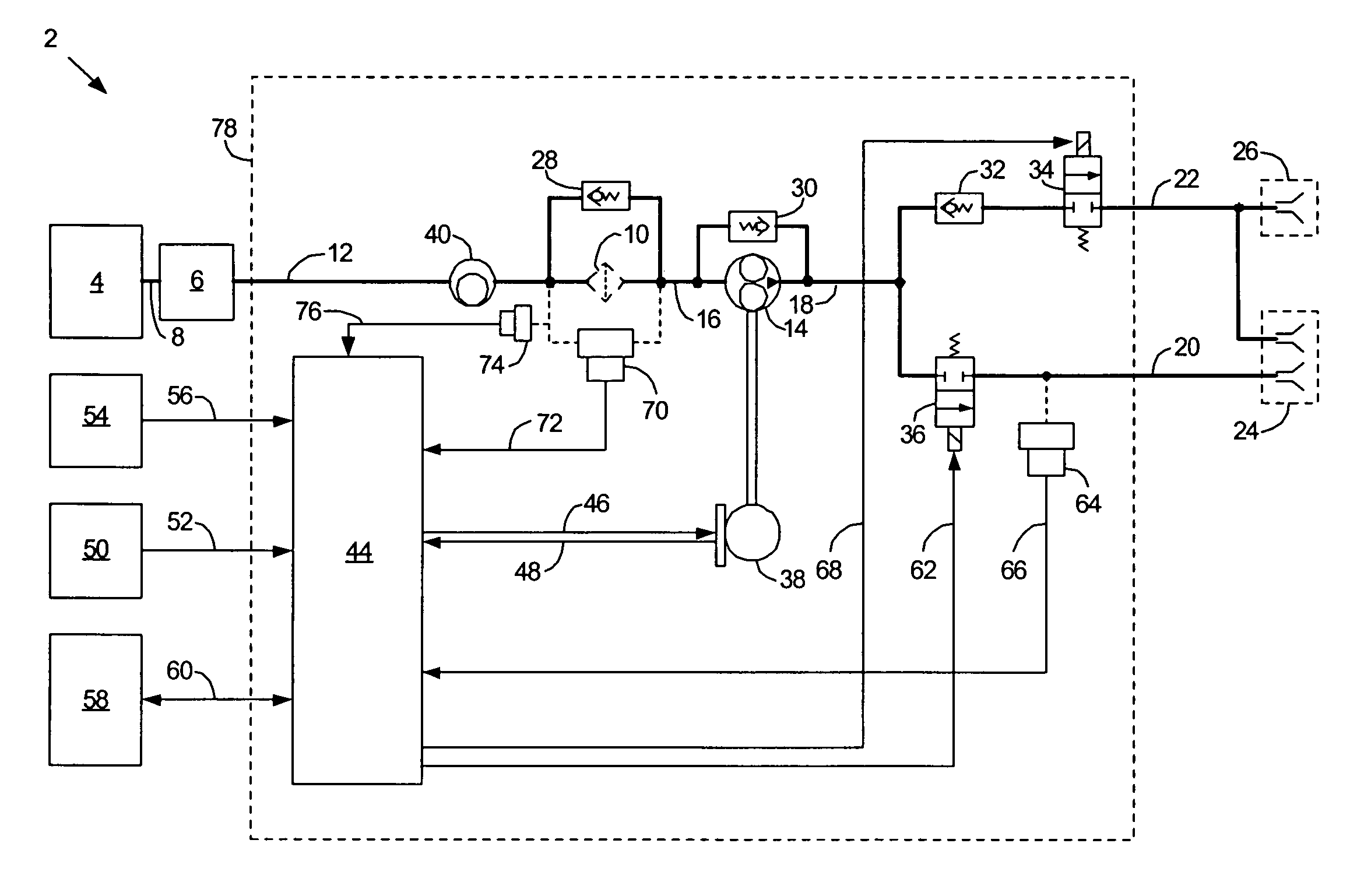
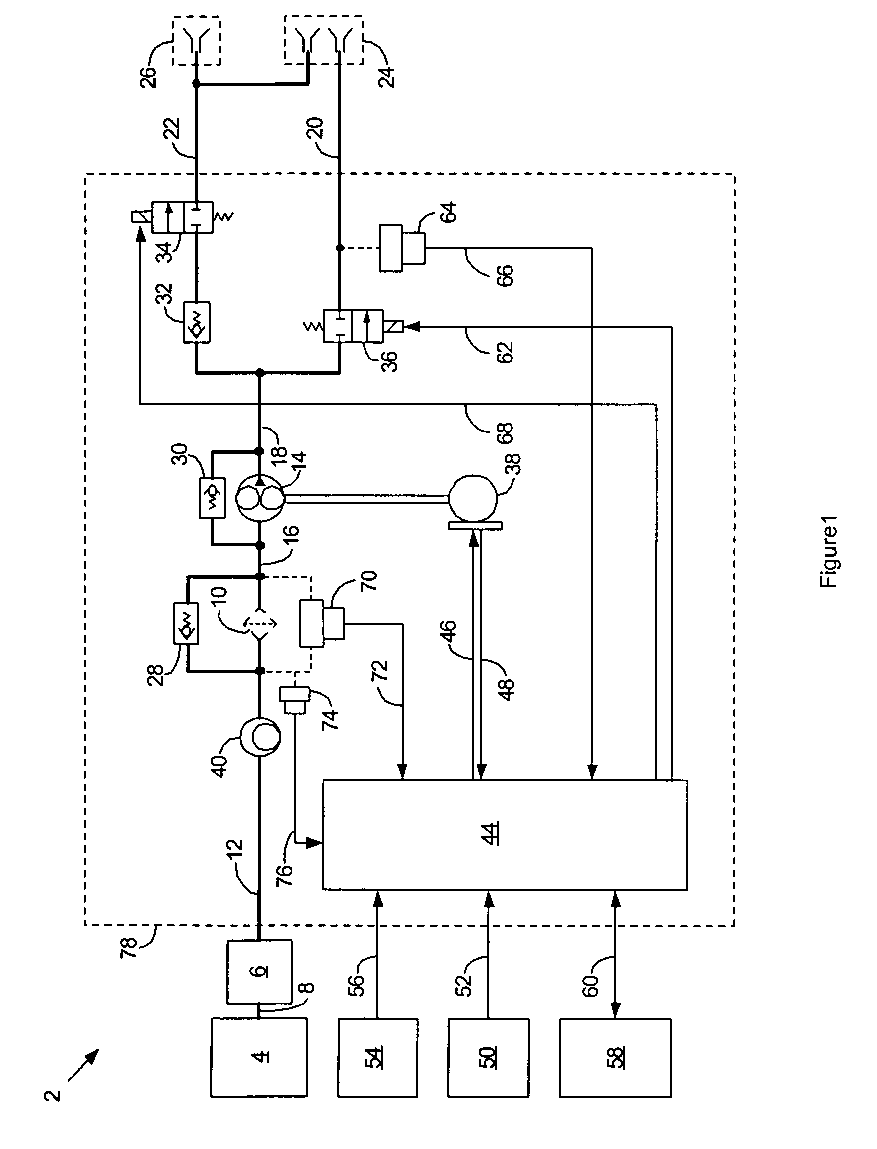
[0008]FIG. 1 is a schematic diagram of a fuel control system 2 for a gas turbine engine according to a possible embodiment of the invention. Fuel from a fuel supply source 4 feeds a spar valve 6 through a fuel supply line 8 for manual control of fuel flow. A fuel filter 10 filters fuel that passes through the spar valve 6 by way of a spar valve output line 12. A fuel pump 14, such as a gear pump, pumps fuel that passes through the filter 10 by way of a fuel filter output line 16. The fuel pump 14 supplies fuel through a pump supply line 18 to a start manifold 20 and a run manifold 22 for the engine. Typically, the start manifold 20 and run manifold 22 supply fuel to a plurality of duplex nozzles 24 and the run manifold 22 supplies fuel to a plurality of simplex nozzles 26. The nozzles 24 and 26 inject fuel into a combustor for the engine that ignites to provide engine power.
[0009] A fuel filter bypass valve 28 typically bypasses fuel around the fuel filter 10 in the instance that t...
PUM
 Abstract
Description
Claims
Application Information
 - R&D
- Intellectual Property
- Life Sciences
- Materials
- Tech Scout
- Unparalleled Data Quality
- Higher Quality Content
- 60% Fewer Hallucinations
Browse by: Latest US Patents, China's latest patents, Technical Efficacy Thesaurus, Application Domain, Technology Topic, Popular Technical Reports.
© 2025 PatSnap. All rights reserved.Legal|Privacy policy|Modern Slavery Act Transparency Statement|Sitemap|About US| Contact US: help@patsnap.com


