
Multi-stage variable displacement engine

a variable displacement, engine technology, applied in the direction of combustion engines, cylinders, sealing arrangements of engines, etc., can solve the problem of partial load condition of the engine, and achieve the effect of reducing fuel consumption and optimizing the powertrain efficiency

Inactive Publication Date: 2007-06-14
IND TECH RES INST
View PDF11 Cites 56 Cited by
  • Summary
  • Abstract
  • Description
  • Claims
  • Application Information

AI Technical Summary

Benefits of technology

[0003] In view of the disadvantages of prior art, the primary object of the present invention is to provide a multi-stage variable displacement engine with uneven cylinder displacement arrangement for enabling the engine to have multi-stage displacement capability adapted to various vehicle driving conditions so as to optimize the efficiency of the powertrain and thus reduce fuel consumption.

Problems solved by technology

However, when an automobile is running in an urban area as it does most of the time, its engine is subjected to a partial-load condition that the engine is not operated in the fuel saving zone.
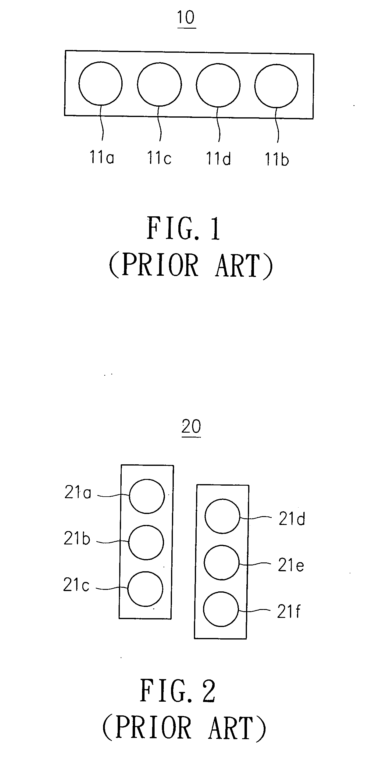
However, since the displacements of individual cylinder of each aforesaid conventional engine are all the same as each other, those conventional engines are only capable of switching between two mode of displacements, i.e. each can only be switching between full displacement and half displacement.

Method used


Image

  • Multi-stage variable displacement engine
  • Multi-stage variable displacement engine
  • Multi-stage variable displacement engine

Examples


Embodiment Construction

[0021] For your esteemed members of reviewing committee to further understand and recognize the fulfilled functions and structural characteristics of the invention, several preferable embodiments cooperating with detailed description are presented as the follows.

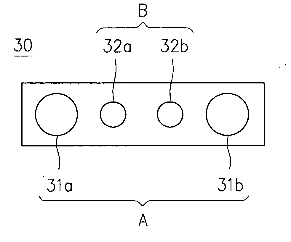
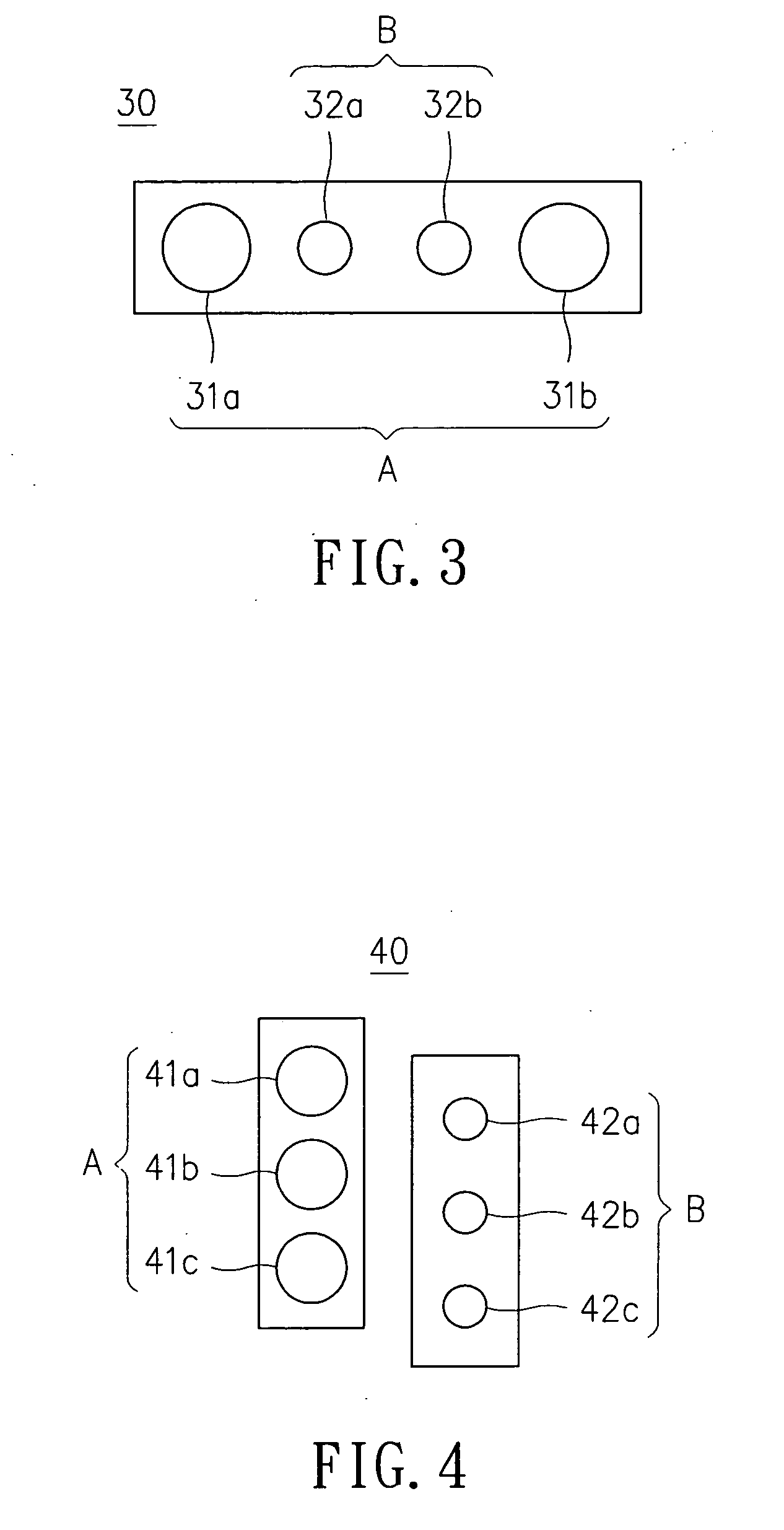
[0022] Please refer to FIG. 3, which is a schematic diagram illustrating the application of a cylinder configuration of the present invention upon an inline multi-cylinder engine according to a preferred embodiment of the present invention. The inline multi-cylinder engine 30 has four cylinders 31a, 31b, 32a, 32b. The cylinders 31a, 31b, being the odd-numbered cylinders with respect to a specific ignition sequence, are grouped into group A. The cylinders 32a, 32b, being the even-numbered cylinders with respect to the specific ignition sequence, are grouped into group B. The cylinder bores of the two odd-numbered cylinders 31a, 31b of group A are the same, and the cylinder bores of the two even-numbered cylinders 32a, 32b of...


PUM


Abstract

The present invention relates to an uneven cylinder displacement arrangement of a multi-stage variable displacement engine. By arranging a plurality of cylinders of at least two different cylinder bores or at least two different strokes in an engine while grouping the plural cylinders into at least two cylinder groups, e.g. grouping odd-numbered cylinders in an ignition sequence of the engine into a first group while grouping even-numbered cylinders in an ignition sequence of the engine into a second group, the engine is enabled to have multi-stage displacement capability adapted to various operation speeds for reducing fuel consumption since the displacement of the engine can be varied by using the ignition sequence to control and select which groups are to be ignited for matching the current load of the engine. In a preferred embodiment of the invention, there are two kinds of cylinders of different cylinder bores arranged in an engine which are grouped into two cylinder groups by the control of the ignition sequence of the engine, whereas the cylinder bore of a cylinder grouped in one of the two cylinder group is the same as another cylinder of the same cylinder group, but is different to those grouped in another cylinder group.

Description

FIELD OF THE INVENTION [0001] The present invention relates to a multi-stage variable displacement engine, and more particularly, to an engine with uneven cylinder displacement arrangement for enabling the engine to have multi-stage displacement capability adapted to various vehicle driving conditions so as to optimize the efficiency of the powertrain and thus reduce fuel consumption. BACKGROUND OF THE INVENTION [0002] Most common automobile internal-combustion engines are operated with better fuel consumption as they are subjected to a high-load condition while engine is running around at the speed from 2000 rpm to 3500 rpm, i.e. the fuel saving zone of an engine commonly falls in those running conditions. However, when an automobile is running in an urban area as it does most of the time, its engine is subjected to a partial-load condition that the engine is not operated in the fuel saving zone. Conventionally, to improve the fuel economy of automobile, a valve actuation control t...

Claims


Application Information

Patent Timeline
Patent Type & Authority Applications(United States)
IPC IPC(8): F02B75/04F02B75/22F02B75/20F02F1/00F02F11/00
CPCF02B73/00F02B75/20F02D13/06Y02T10/18Y02T10/12
Inventor SHEI, TSUNG-WEI
Owner IND TECH RES INST
Learn More