Cooking appliance

a technology for cooking appliances and cooling elements, which is applied in the field of cooking appliances, can solve the problems of affecting the efficiency of cooking appliances, the inability to efficiently cool the electric element chamber, and the inability to efficiently cool the blowing fan in the conventional cooking appliances, so as to reduce thermal damage, improve energy efficiency, and efficiently cool the elements

Active Publication Date: 2007-06-14
LG ELECTRONICS INC
View PDF4 Cites 37 Cited by
  • Summary
  • Abstract
  • Description
  • Claims
  • Application Information

AI Technical Summary

Benefits of technology

[0012] An object of the present invention is to provide a cooking appliance having a structure capable of efficiently cooling elements received in an electric element chamber.
[0013] Another object of the present invention is to provide a cooking appliance capable of achieving an increase in energy efficiency.
[0014] Still another object of the present invention is to provide a cooking appliance capable of reducing thermal damage applied to a cabinet receiving the cooking appliance when the cooking appliance is of a built-in type.
[0019] The exhaust duct may have a straight portion extending to a predetermined length at an outlet end of the exhaust duct, to prevent diffusion of air outwardly discharged from the exhaust duct.
[0031] The top plate may have a stepped end in a region where the ambient air intake louver is arranged, to prevent water form being externally introduced into the electric element chamber through the ambient air intake louver.

Problems solved by technology

In such conventional cooking appliances, however, there is a problem in that the electric element chamber cannot be efficiently cooled because a motor for driving the blowing fan is arranged in a flow path of blown air.
Furthermore, the blowing fan equipped in the conventional cooking appliances has a drawback of a degradation in energy efficiency because it directly sucks a flow of heated air present in a cooking chamber.
As a result, there is a problem in that the cabinet may be distorted.

Method used


Image

  • Cooking appliance
  • Cooking appliance
  • Cooking appliance

Examples


Embodiment Construction

[0043] The particulars shown herein are by way of example and for purposes of illustrative discussion of the embodiments of the present invention only and are presented in the cause of providing what is believed to be the most useful and readily understood description of the principles and conceptual aspects of the present invention. In this regard, no attempt is made to show structural details of the present invention in more detail than is necessary for the fundamental understanding of the present invention, the description taken with the drawings making apparent to those skilled in the art how the several forms of the present invention may be embodied in practice.

[0044] Reference will now be made in detail to the preferred embodiments of the present invention, examples of which are illustrated in the accompanying drawings. Wherever possible, the same reference numbers will be used throughout the drawings to refer to the same or like parts.

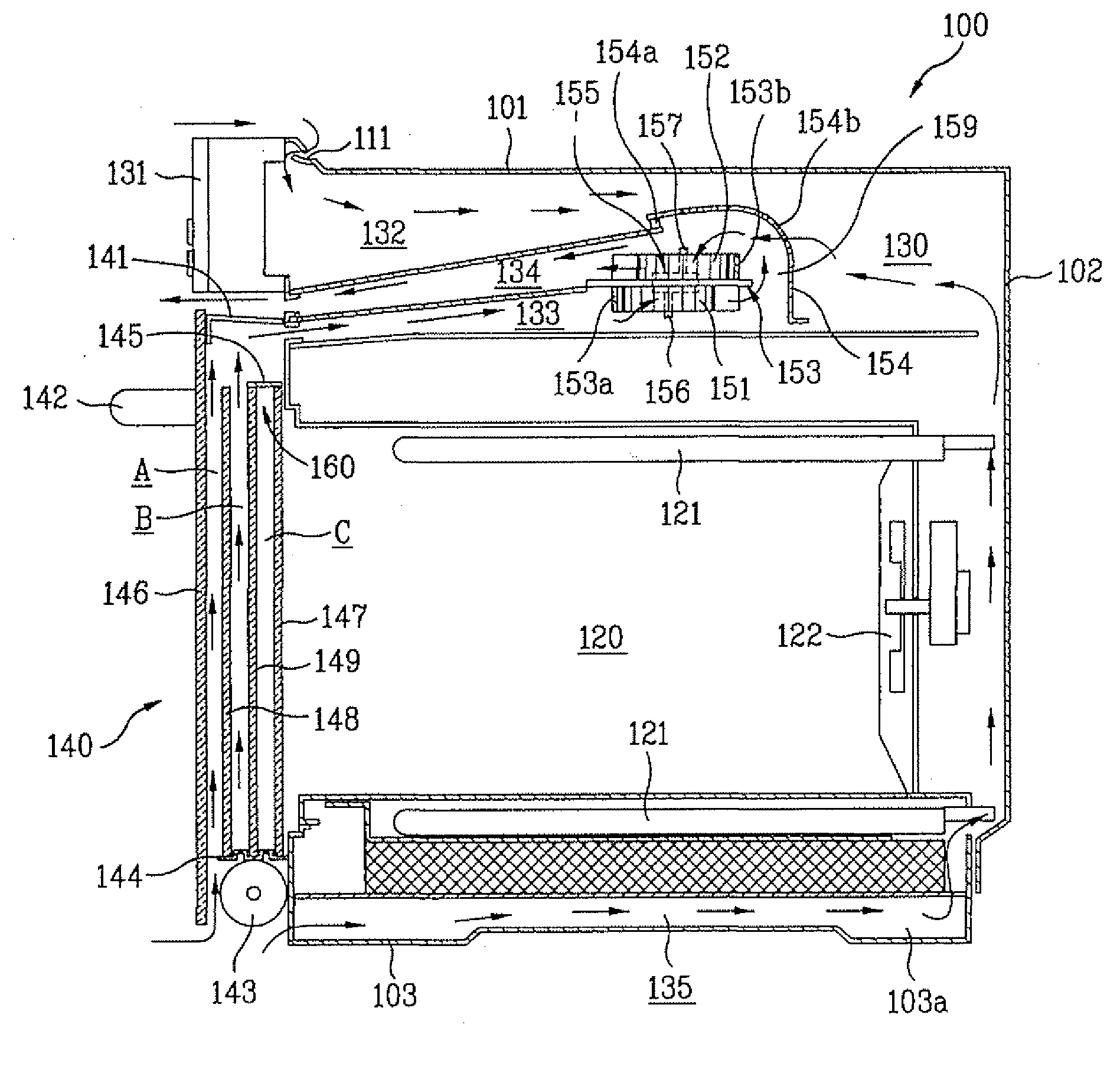
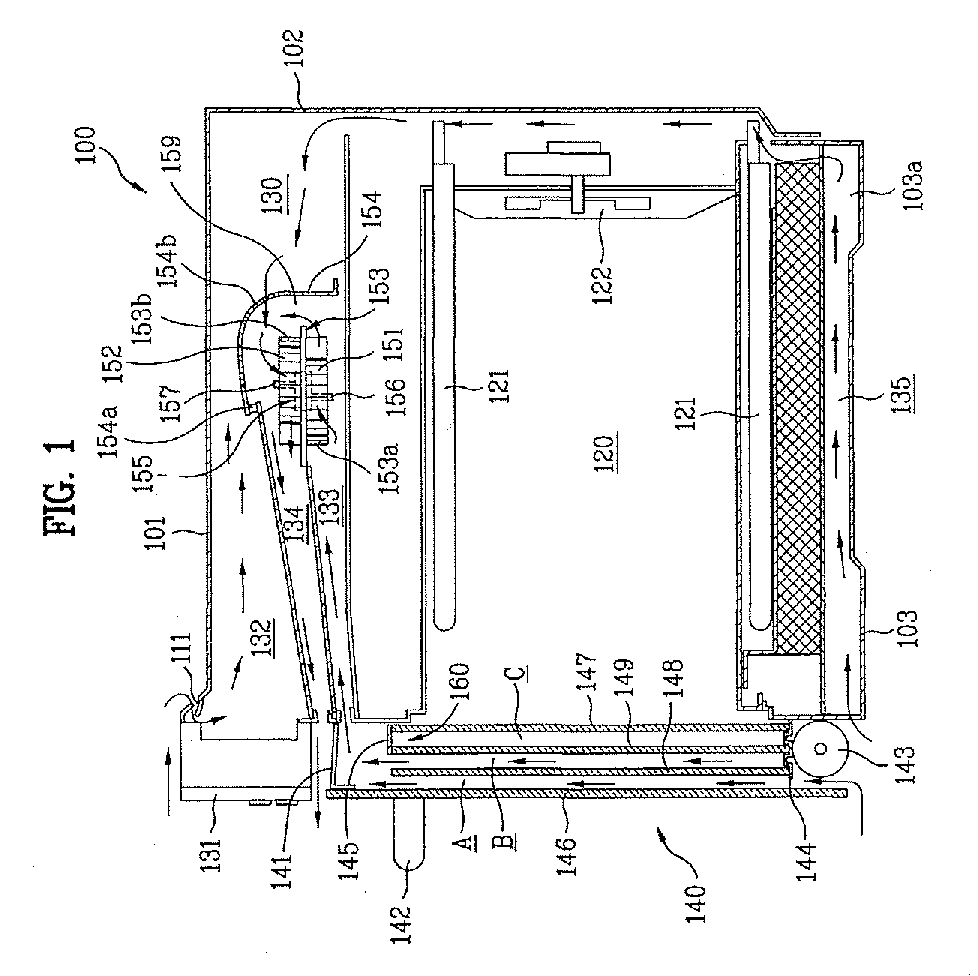
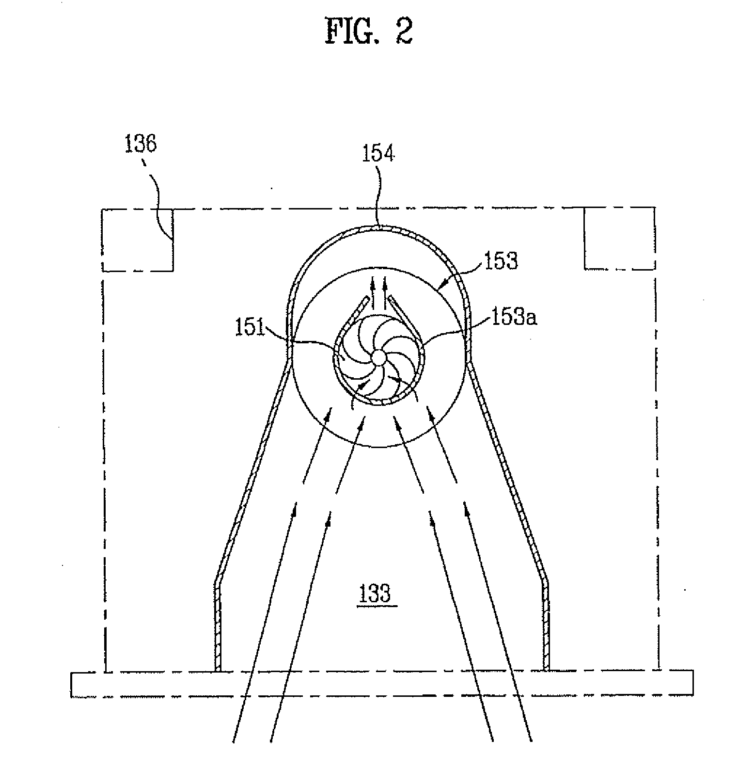
[0045] Hereinafter, a cooking appliance...


PUM


Abstract

A cooking appliance is provided that has a structure which efficiently cools an electric element chamber. The cooking appliance includes an appliance body that has a cooking chamber to cook food, a door that opens and closes the cooking chamber, and cooling flow passages that absorb heat transferred from the cooking chamber. Additionally, an intake air duct may be provided proximate a top side of the cooking chamber to communicate with the cooling flow passages. Further, an exhaust duct may be provided proximate the intake air duct to communicate with the intake air duct. Further, a fan-motor assembly may be provided in a space formed by the intake air duct and the exhaust duct such that the fan-motor assembly forms a portion of a connecting passage that connects the intake air duct and the exhaust duct.

Description

[0001] This application claims the benefit of Korean Patent Application No. 10-2005-0121829, filed on Dec. 12, 2005, which is hereby incorporated by reference as if fully set forth herein. BACKGROUND OF THE INVENTION [0002] 1. Field of the Invention [0003] The present invention relates to a cooking appliance, and more particularly, to a cooking appliance having a structure capable of efficiently cooling elements received in an electric element chamber. [0004] 2. Discussion of the Related Art [0005] Generally, for cooking appliances, various products such as an oven and a microwave oven are known. The microwave oven is an appliance for cooking food using a magnetron alone or together with a heater. On the other hand, the oven is a cooking appliance designed to boil food using a dry heat by heating the food in a sealed chamber. In this case, electricity, gas, or the like is used as a heat source for supplying heat to the food. [0006] In particular, electric ovens are favorable to cons...

Claims


Application Information

Patent Timeline
Patent Type & Authority Applications(United States)
IPC IPC(8): F24C15/32
CPCF24C15/006F24C15/02F05D2250/52F04D17/164F04D29/4226F04D29/441H05B6/642F24C7/04F24C15/32
Inventor KIM, JONG SIKKIM, YANG KYEONG
Owner LG ELECTRONICS INC
Why Eureka
Try Eureka